Appearance
Cops
New cops
Overview
In mid 2024 Sidefx released Houdini 20.5 and Copernicus, a welcome update and rewrite of Houdini's compositing toolkit.
It fixed a lot of the issues people had with old cops, added a few more tools, is generally pretty awesome.
The downside is that a lot of my notes here are out of date, at least all my complaints. Luckily Sidefx ported most of the old cops nodes to new cops, so you can still follow along. Here's the broad strokes of whats changed:
- New cops flow left-to-right instead of top-to-bottom
- Cops exist as geometry by default (they're essentially 2d volumes)
- Because they're geo, they have much tighter integration with other sops geo
- There's a lot more substance designer style nodes in there now
- It can support doing slap comps for solaris live in the viewport, ie you can setup a comp workflow, and the input is taken direct from the viewport, and exported back to the viewport live.
There's more, sidefx (and others) have already put out some great video lessons, go watch.
I'd say that the general vibe and intent of my older cops notes are still valid; you can still write vex (even easier than old cops), you can sample and warp pixels in similar ways, you can do tricks that aren't as easy to do in Nuke or After Effects.
Dome visualisation
Download hip: cops_the_sphere_outside.hip
Paul Esteves asked an interesting question; would it be possible to do visualizations for doing Vegas 'The Sphere' style graphics, but realtime with cops?
40 mins later I had this nice little prototype. You could do this with old cops, but it'd be a little slow and unreliable.
The core idea is relatively simple; steal some spherical projection code from the original mantra ASAD lens shader, use it to drive a vex intersect call. Do some cheaty lookups for colour, fake a lighting pass, done.
You could lookup Konstantin Magnus's great cops renderer example to extend this to support textures, occlusion, a few other things.
The actual visualisation takes advantage of how fast new cops works with the rest of houdini; the texture is fed to a uvquickshade node running on another sphere. Super fun stuff.
Dome with flipped rays
Download hip: cops_the_sphere_outside.hip
A trick this setup can do that you can't with a regular fisheye lens is to play with the origin and direction for the intersect call.
The outside setup assumes for a camera at the origin, and tracing rays out onto a sphere. But you can flip this, set the rays to start from the sphere surface, and trace a ray back towards the origin.
vex
// trace from origin and out
int prim = intersect(1, origin, dir, pos, uv);

// trace from sphere surface and in
int prim = intersect(1, dir+dir*0.03, -dir, pos, uv);
// trace from origin and out
int prim = intersect(1, origin, dir, pos, uv);
// trace from sphere surface and in
int prim = intersect(1, dir+dir*0.03, -dir, pos, uv);Notice how the balls are small when near the sphere surface, and get bigger the further away they are? I realised in hindsight this setup basically acts like its tracing rays from the surface of a glass sphere, magnifying and inverting things the further they are from the sphere surface.
Because it's vex, its ripe for experimentation. Warp the start points with noise? Wobble the trace direction? Trace from the surface of a pig instead of a sphere? Modify the results with other new cops tricks? Endless possibilities.
Old Cops
I'll keep the old notes around for legacy, but will make sure to classify them here in this 'old cops' section.
Overview
Mike Lyndon has done a great overview of Cops, definitely worth watching: https://vimeo.com/247302953
Cops is Houdini's built in compositing network. In theory its powerful, but in practice its one of the older systems within Houdini and needs some love. If you're in the market for an unstable and slow compositor, Cops has you covered.
It's a little frustrating, as there's tricks you can do in cops that are hard or impossible in any other system. Writing vex and vops filters is one thing, but being able to query geometry attributes in 3d and read them into pixels directly, without requiring an expensive render to do raycasting, is a pretty cool trick. It's the secret sauce behind the Sidefx Labs VAT tools and fast baking operations.
You can also directly refer to cops nodes where you would otherwise use a texture path. Just put in the path to the node, eg /img/OUT_cool_cop, then go back and prefix it with op:, so the path would look like
op:/img/OUT_cool_cop
Just note that this cook chain starts to get unstable, and sometimes you'll find the textures aren't updating when you want, or go the dreaded pale pink (meaning it couldn't find the texture), or you get garbled results... all the joys of working with Cops.
Still, every time I swear I'll never use Cops again, I end up using it. Bad cops bad cops, whatcha gonna do?
Disable thumbnails
A surprising performance hit comes from the thumbnails that cops uses by default, best to turn them off. You can do this in the preferences ( Edit -> Preferences -> Network Editor, Nodes and Trees), and turn off 'Show previews on New COP Nodes'.
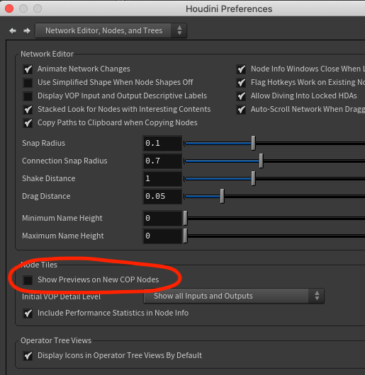 On an existing network you'll need to select all the nodes, r.click and choose Flags -> Thumbnail

Hide on screen controls
Some of the tools can get a bit busy and distracting on screen, you can toggle them with the stow-menu on the right of the viewer.

Viewport crop
I turned this on by accident one time, lost a day trying to figure out what I did. A coworker recently did the same, luckily it only took me 5 mins to remember this time. Writing it down here so no-one else has to suffer!
Define a crop with shift and left-mouse-button drag:
And most importantly, get rid of the crop with shift and middle-mouse-button click:
Cops and Vex and copinput
 Download scene: cop_vex.hipnc
There's no Cops wrangle yet, boo.
Cops Vop with a snippet works though, yay!
It still feels a little crusty (why all capital letters? Why X Y R G B A as separate attributes rather than P and Cd?) , but still fun to play with.
If you're doing straight colour manipulation, that's simple enough, read the incoming rgba, modify, write it out.
If you're transforming pixels (say a rotate or a warp) the workflow is different; it's similar to a primuv call in that you request an xy position, it returns a value. You essentially define a warped uv map which is used as a lookup to distort your image.
The vex functions to do this are cinput() binput() finput(), which return low/mid/high quality results.
cop input wraps these up in a vop, which keep everything nice and modular. Define your uv coords in a wrangle, append a cinput vop, and you get your distortion in fast/mid/slow flavours from a combo box.
So to do a sine ripple to an image, you put down a cop vop filter, dive inside, make a snippet, wire in X and Y, and modify X like:
vex
vector2 pos = set(X,Y);
pos.x += sin(pos.y*60)*0.02;
X = pos.x;
Y = pos.y;
vector2 pos = set(X,Y);
pos.x += sin(pos.y*60)*0.02;
X = pos.x;
Y = pos.y;That then feeds the u and v inputs of a cop input, set the output signature to 4D vector (ie rgba), then split that vector back into individual floats, and wire to RGBA.
Global inputs are directly available
Not many people do cops stuff, was fun to watch Konstantin at work and see what's possible. A handy thing I learned was inputs are available without needing to wire them from the global inputs to the snippet:
float foo = R;

Global outputs are directly settable with assign()
Similarly Konstantin showed you can export your results directly, no wiring required:
assign(R, G, B, mycol);
For emphasis, no really, cops wrangles are super clean
Previous attempts at cops wrangles (which you can see below) used the inputs and outputs on a snippet. You don't need to. All the global inputs are available, all the global outputs are assignable. Great for quick prototyping, you don't need to be distracted with any vops stuff until you want to start making UI, similar to working with geometry wrangles.
Dare I say it, this might be even easier and faster than using the Nuke Expressions node which I've written a lot about!
Check it:

Sample 3d geometry in cops
 Download hip: cops_geo_sample.hip
As I write this the sidefx labs team have just released a wrapped up Cops node called Attribute Import, but good to know anyway.
You have geo with attributes, it has clean non overlapping uvs, you want to unwrap it to a texture in cops.
The vex uvsample function can do this for you. Just specify the geo to sample, the attribute you want, the uv attribute on the geo (probably @uv), and the actual uv coordinate to lookup, which in cops would be the 0-1 xy coordinate of each pixel. Set this as the pixel colour, done.
vex
vector2 xy = set(X, Y);
vector col = uvsample(geo, 'N', 'uv', xy);
assign(R, G, B, col);
vector2 xy = set(X, Y);
vector col = uvsample(geo, 'N', 'uv', xy);
assign(R, G, B, col);Paul at Sidefx will be the first to jump on me, in that this will be sliiiiightly off if you have really high res detail; you want to ensure you're sampling at the center of each pixel, not the corner, so you shift the uv lookup position by half a pixel. But if you're that precious about perfect results, you may as well use the labs tool. 😃
Bake texture between uv layouts

Download hip: cops_uv_rebake.hip
Closely related to the previous topic (and several of the following topics), its not uncommon to have a texture designed for one uv layout, then have the uv's change. How can you generate a new texture that matches the new uv layout?
You could send stuff back to substance, or bake in the renderer, but if you think about it this should be a straightforward question of 'where do I move this pixel?', which you can do with cops.
In this example I have the pig, I do an autouv, and I need to generate a new texture to match. From inside a vex snippet, the refined question is really 'I am a pixel in the new texture. How can I find what colour I'm meant to be from the old texture?'. It's a reverse lookup, which took my brain a few moments to realise (my first few attempts did a forward lookup, which was stupid). The pseudocode is basically
from my uv, what is the corresponding P on the new mesh?
from that P, what is the corresponding uv on the old mesh?
from that uv, what is the colour in the texture?
set my colour to that color
from my uv, what is the corresponding P on the new mesh?
from that P, what is the corresponding uv on the old mesh?
from that uv, what is the colour in the texture?
set my colour to that colorThe actual code isn't far removed from this. In the snippet I have 2 constants, 'old' and 'new' that point to the op: paths for the old mesh with old uvs, and new mesh with new uvs:
vex
vector uv = set(X,Y);
vector pos = uvsample(new, 'P', 'uv', uv);
vector uv2 = uvsample(old, 'uv', 'P', pos);
vector col = cinput(0,0, uv2.x, uv2.y);
assign(R, G, B, col);
vector uv = set(X,Y);
vector pos = uvsample(new, 'P', 'uv', uv);
vector uv2 = uvsample(old, 'uv', 'P', pos);
vector col = cinput(0,0, uv2.x, uv2.y);
assign(R, G, B, col);Note that I'm using cinput(), the 'dumb' lookup, vs the properly filtered finput(). Curiously I get a lot more artifacts on seams using the filtered version. Maybe because ultimately this has to be a 1:1 pixel value, not a filter that might get oddball results if islands change or values are near seams? Not sure.
This works, but the texture can look pretty messy. Uvsample will always return some kind of value, even if there's no 'real' value to lookup. So where there's blank regions in the uvs, they'll be smeared to the nearest 'real' value, meaning ugly smeary mess.
I've got around this by branching off the mesh in sops, using a split uv seams sop (and ensuring uvs are transfered to points), then in a wrangle set @P = @uv. I pull that into cops with a geometry cop, which renders a perfect alpha of the uvs. I can then channel copy that over, premultiply, and maybe run an extraploate borders to get a 'nice' border smear vs an ugly smear.
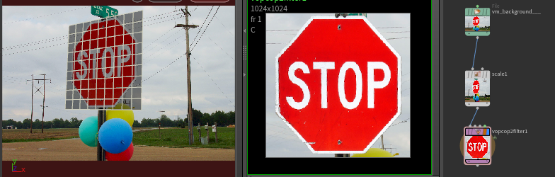
Projection mapping
 Download hip: cops_projection_map.hip
The previous trick can be used to replicate what this blender video is talking about, which is usually called camera projection, or projection mapping, or a simple form of photogrammetry if you want to get fancy. It's a technique folk in commercials were using decades ago, I think the first I became aware of it was probably Buf's work on Fight Club back in 1999.
Anyway, the workflow in Houdini is pretty simple:
- Create a camera, put a background image into it, match the camera position/rotation to the image
- Create a grid, give it basic uvs with a uvtexture sop
- Translate/rotate the grid to match a texture you want to extract
- Append another uvtexture sop, this time with camera uvs from your camera
Jump over to a new copnet:
- load the same background image with a file cop
- scale it to a 1:1 ratio
- append a vop filter
- create 2 float constants, u and v
- create a parm, type 'geometry(string)', named 'geo
- connect all 3 to a snippet, use this wrangle:
vex
vector2 xy = set(X, Y);
vector col = uvsample(geo, 'uv2', 'uv', xy);
u = col.r;
v = col.g;
vector2 xy = set(X, Y);
vector col = uvsample(geo, 'uv2', 'uv', xy);
u = col.r;
v = col.g;- connect the out u and v to a copinput, and that to the out R G B
All this does is return the camera uv's (@uv2), in the flat vanilla uv's (@uv). When this is fed to a copinput, it takes that image and flattens out the region you specified.
Latlong to cubemap
 Download scene: latlong_to_cubemap_v04.hipnc
 Many thanks to Eetu for solving the last bit I was struggling with!
Been doing more and more pano experiments in Houdini lately, but I always have to keep Nuke open to do relatively simple things. A key thing is to be able to transform from a equirectangular/latlong panorama to a cubemap. Having recently worked out how to put a vex snippet in a cop vop, this seemed a good thing to try.
First, I did some intense research on polar maths and space conversion , which led me to this post:
http://stackoverflow.com/questions/29678510/convert-21-equirectangular-panorama-to-cube-map
The trickiest part here was taking the python answer, and translating it into vex. Not the language per se, but taking the sequential method of the python example ('for every pixel in the images do this...') and making a parallel processing version in vex. The python example also has lots of code for anti-aliasing, which wasn't a concern here as the cinput vop takes care of all that.
Anyway, got it all ported and... it was almost right. Could see the N/S/E/W planes were sort of working, but the top and bottom were skewed. At that point it was past midnight, so I posted my work in progress to the discord houdini chatroom.
In the morning, Eetu found the fix, amusingly using a technique similar to mine; try and understand the logic behind it, work out where the fix should be, find it didn't work, then randomly insert multipliers here and there until one started to move things in the right way, then playing with that number until its fixed. At some point I'll go back and try and understand why, but not right now.
To show-off, you can slide the pano horizontally (making sure wrap is enabled), and you get that cool cube tumble effect. I also show off that handy feature of houdini to use http paths to images. I'd planned to use the panos that ship with Houdini in $HFS/houdini/pic/, but annoyingly they're in a houdini cubemap format already, and to unpack those into a latlong, then back to cubemap, seemed more effort than it was worth.
The idea behind the code is to treat the image as a new blank cubemap, and work out where to lookup the corect values from the latlong. First it identifies the NSEW zones, which are every 1/4 across the image. Then it divides the image vertically into thirds, and defines the top third as top of the cube, and bottom third as bottom of the cube.
Now that it knows the regions, it calculates the uv position on the sphere using the previously defined outImgToXYZ function. This does a conversion from the 2d cubmap positions into 3d sphere positions. This is then used to get the polar coordinates (ie, the compass direction, or theta, then the up/down angle, or phi), to find the pixel we need on the latlong, which is in turn used to drive the copinput vop.
The top and bottom regions will cover the entire top and bottom strips, so I make a mask based on the regions to multiply the results against later to get a clean cubemap image. You can bypass the multiply1 node to see the effect of this.
80s stuff
 Download hip: retro_cyan.hip
This odforce post on wireframe rendering made me try a few things I've wanted to have a go at, which I'll sum up as 'retro kitsch'.
Scanlines are easy enough, vopcop filter, combine the R G B channels into a single Cd vector, and X and Y into a P vector, then run this in a snippet:
vex
float scanline = clamp(sin(P.y*YRES),0,1);
scanline = fit(scanline,0,1,0.6,1);
Cd*=scanline;
float scanline = clamp(sin(P.y*YRES),0,1);
scanline = fit(scanline,0,1,0.6,1);
Cd*=scanline;At one point I wanted to test an effect, and needed a grid. Vopcop2 generator, snippet, thus:
vex
float linewidth = 0.002;
float gridsize=0.04;
Cd  = P.x % gridsize < linewidth ?1:0;
Cd += P.y % gridsize < linewidth ?1:0;
float linewidth = 0.002;
float gridsize=0.04;
Cd = P.x % gridsize < linewidth ?1:0;
Cd += P.y % gridsize < linewidth ?1:0;Next was a chromatic aberration effect, which is basically a radial distort that is mostly 0 at the center, and increases at the edges, applied slightly differently to the r/g/b channels.
The core of the distort is this in a snippet:
vex
float d  = distance({0.5,0.5},P);
d = smooth(0.2,2,d);
d*=0.05;
vector2 disp = set(d,d);
if (P.x<0.5) {
 disp.x*=-1;
}
if (P.y<0.5) {
 disp.y*=-1;
}

P +=disp;
P-=0.5;
P*=0.9;
P+=0.5;
float d = distance({0.5,0.5},P);
d = smooth(0.2,2,d);
d*=0.05;
vector2 disp = set(d,d);
if (P.x<0.5) {
disp.x*=-1;
}
if (P.y<0.5) {
disp.y*=-1;
}
P +=disp;
P-=0.5;
P*=0.9;
P+=0.5;That then drives 3 copinput vops as before (each beign run through an addconstant to slightly increase/decrease the effect for each channel, then combined.
That, plus some blurs, convolves, other hacky things, made something I was kinda happy with.
Using cops as a renderer
 Download hip: cops_render.hip
Cops lets you query info from sops via vex. The Sidefx Labs Maps Baker tool uses this by looking up uv's and querying sops normals, positions, other attributes, and bake them down into images in cops.
uvsample() is one vex call to do this; give it a uv position, ask it for an attribute to return at that uv position, go do stuff. In cops you can use the current pixel X Y as the uv location to query, fun abounds.
It then raised the question; if you can do this in uv space, could you do it in other ways, say camera space? I asked Paul Ambrosiussen, who said yep, you just need to get your uv values via whatever means, and you can do what you want.
This lead me to the intersect() and fromNDC() vex functions. The idea being this:
- For each pixel in cops, get its position in camera space
- Project that pixel into the scene, if it hits some geo, get the uv at that location
Early tests proved promising, I could then run those results to the copinput vop and see textured geo. While googling for vex help I stumbled across an odforce post and youtube vid by Konstantin Magnus:
https://www.youtube.com/watch?v=iDeE_XtaKk0&t=2s&ab_channel=KonstantinMagnus
Not only did he get the uv sample, Konstantin was running lights, shadows, reflection, occlusion... I was struggling to play with duplo blocks, then looked and seen he'd made the Eiffel Tower out of Technics. Ouch.
At any rate, his video let me get through the process much faster, and it all worked great.
One thing Konstantin didn't touch (or that I didn't see a solution for) was to link the houdini camera focal length to this setup. Konstantin had an arbitrary 'zoom' factor, I was hoping to find a way to make it be directly driven from the camera.
This is where fromNDC() came in; you give it a camera path, it will reformat the input point values as if they were rendered through the camera. Perfect, except... it doesn't work in cops. In sops and in a mantra render its perfect, but in cops it gave glitchy results, a throwaway line in the help said
"fromNDC may not be well defined outside of sops/mantra/light context."
Doh.
After a day of swearing, I found the workaround; the perspective() call. This will generate a matrix to do the perspective projection of a camera, but this too had a throwaway line that was annoyingly obtuse:
"If you want the world-to-camera matrix, it's simply worldToNDC = transform * projection"
Much swearing later, I got it work, helpfully by doing it in sops first, then matching colours between cops and sops until it did what I expected (hence this hip setup).
SO:
- Get your sample positions as a 0:1 square, centered at the origin
- Multiply the sample positions by the perspective() matrix, which scales the sample values the right amount for the focal length
- Move those values forward a bit in z, then multiply by the camera transform, which puts those sample positions in front of the camera, like a 'lens'
- Calculate a vector from the camera focal plane to each sample point. This is the ray direction to fire out into the scene
- intersect() to fire said ray from the sample point into the scene, return what prim it hit, what intrinsic uv is at that location
- Use primuv() to query the human friendly texture uv at that prim+intrinsic uv value
- Feed that to copinput to get a textured version of the scene
There's devil in the details (the focal length calculation needed fudging, I still don't think I'm exactly right with some of the stuff), but it works well enough for my needs, and more interestingly this is all open for play.
The comparison I keep making is this is similar to the scanlinerender node in Nuke, but completely programmable. It's also interesting in that it sits somewhere between the opengl rop and a mantra rop; its slower than opengl, but faster than mantra, its as programmable as a mantra material, and also sits within cops so all the silly 2d tricks you might want to use are available, the camera can be fudged as much as you to do whatever other crazy non-standard camera tricks you could desire.
Fun stuff.
Using animated cops in sops
 You can use cops directly with sops by just drag-n-dropping the cops node onto a texture path, and then prefix it with 'op:'.
A key annoyance is if the cops graph is animated, you often won't see it update in sops, forcing an annoying need to render the cops sequence out, and refer to an on disk path like c:/render/damnitcops.$F4.png.
Turns out this is by design. If you want the live path, append [$F]. So
op:/obj/geo1/cop2net1
becomes
op:/obj/geo1/cop2net1[$F]
You can also refer to any frame in the same way, eg pull in only frame 10:
op:/obj/geo1/cop2net1[10]
Extrapolateboundaries
 Edge smear, edge extend, max edges, edge padding, texture fill, fill borders UV alpha, expand image borders. Right, I think that's every possible combo of SEO terms I can think of for this very handy node.
Often when working with textures and uv seams, you need to smear colour beyond the uv shell borders to avoid artifacts. It also comes up when working with premultiplied vs unpremultiplied alpha, and you just want to extend the colour a little bit beyond the alpha edge.
I've done this too many times by using an edge detect to get the border on the alpha, copy that alpha back to the original source, blur, dilate, more work, then composite that result under the original image. That's whats shown in the image above, on the left, and the red nodes.
Dave Brown was doing a similar thing and put down a single node, extrapolateboundaries, shown above on the right, the single green node. Does all the stuff I was trying to do, faster, better.
Don't make the same mistake I did. Stash extrapolateboundaries in your brain, it'll save you one day.
Triplanar texture baking like substance
 Download hip: cops_triplanar_bake.hip
The aircraft chassis is from Sketchfab: https://sketchfab.com/3d-models/fortnite-plane-cc1274df0f0845df8da7af3fe3053f57
The grimy texture is from Polyhaven: https://polyhaven.com/a/rusty_metal_02
The labs maps baker has hinted for a while that cops could be used for substance style tricks. I'd been playing around with this for some work tasks, but when cleverman Adam Swaab showed a very nice bake result for another work challenge, I felt compelled to finish what I started.
Substance has a nice trick where as long as you have nice uv's on your object, you can setup whatever combo of paint, procedurals, 'smart materials', texture projections, and the final result will be baked down to match the uv's of your mesh. This is especially handy and effective where a nice texture map can be projected along the global X/Y/Z, blended where the normals transition from one angle to another, and baked. To replicate that with cops is pretty simple:
- Store the bounding box values of a shape as colours
- Take pairs of those values, say the red and green, use that to define an orthographic uv projection along X, Y, Z
- Get the normals of the object, compare those against the world X,Y,Z with a dot product
- Take a texture, map it into those 3 uvs, and blend them depending on how much they face along X/Y/Z.
The surface properties like N and the bounding box stored as colour on points can be pulled into cops with the Labs Attribute Import cop. The processing and baking is done in a vop filter, where I use a vex snippet to do all the heavy lifting. The handy function here is finput(), where you specify which cops channel to lookup and a uv coordinate, and it'll return the filtered colour.
What we can also do is use all the great mask by occlusion/measure curvature stuff in sops to generate nice point level grime and countours, and multiply that against our baked triplanar map.
The full vex snippet looks like this, which has extra controls to toggle if it'll multiply the occlusion/curvature against the map, a debug mode to tint the projections R G B, and how much to blend the different projections:
vex
vector Cd, maskx, masky, maskz, tintx, tinty, tintz;

if (debug) {
    tintx = {1,0,0};
    tinty = {0,1,0};
    tintz = {0,0,1};
} else {
    tintx = tinty = tintz = 1;
}

maskx = abs(dot(N, {1,0,0}));
maskx = fit(maskx,min,1,0,1)*tintx;
masky = abs(dot(N, {0,1,0}));
masky = fit(masky,min,1,0,1)*tinty;
maskz = abs(dot(N, {0,0,1}));
maskz = fit(maskz,min,1,0,1)*tintz;

// finput(0,0 refers to the first plane, ie, the tex input
// the different bb.* pairs define uv coordinates to rotate the texture
Cd  = finput(0,0,bb.z, bb.y)*maskx*tintx;
Cd += finput(0,0,bb.x, bb.z)*masky*tinty;
Cd += finput(0,0,bb.x, bb.y)*maskz*tintz;
if (wear) Cd *= set(col.x,col.x,col.x);
assign(R, G, B, Cd);
vector Cd, maskx, masky, maskz, tintx, tinty, tintz;
if (debug) {
tintx = {1,0,0};
tinty = {0,1,0};
tintz = {0,0,1};
} else {
tintx = tinty = tintz = 1;
}
maskx = abs(dot(N, {1,0,0}));
maskx = fit(maskx,min,1,0,1)*tintx;
masky = abs(dot(N, {0,1,0}));
masky = fit(masky,min,1,0,1)*tinty;
maskz = abs(dot(N, {0,0,1}));
maskz = fit(maskz,min,1,0,1)*tintz;
// finput(0,0 refers to the first plane, ie, the tex input
// the different bb.* pairs define uv coordinates to rotate the texture
Cd = finput(0,0,bb.z, bb.y)*maskx*tintx;
Cd += finput(0,0,bb.x, bb.z)*masky*tinty;
Cd += finput(0,0,bb.x, bb.y)*maskz*tintz;
if (wear) Cd *= set(col.x,col.x,col.x);
assign(R, G, B, Cd);Tim has pointed out a few optimisations that can be applied to that vex snippet, will get to that eventually!
An annoying thing with cops vops is you can't easily get to the different image planes by name, its all by index, and even then, has to be driven by a constant rather than just being exposed as a parameter. Silly cops.
I also tried in this setup to generate matching roughness and metalness maps, which more or less work as advertised. These just use lookup cops to run the baked result through a colour ramp.
What surprised me was how fast it runs; I can swap input models, and get a result within about 3 seconds. Not bad for crusty old cops.
Cellnoise with rotated gradients
 Download hip: cops_cellnoise_rotated_ramps.hip
Interesting question on the sidefx forum regarding generating paint flakes. My understanding is they wanted randomly rotated gradients multiplied over cellnoise. I'd done semirelated work with generating uv's for texture splatting, figured I could repurpose some of those ideas here.
First, I need a uv gradient per cell. The cellnoise vop outputs 'center', which is unsurprisingly, the center of each cell. So if you subtract that from the (X,Y), that should give you a uv gradient per cell:
 That's got (0,0) at the center, we'll subtract or fit this so its (0,0) at one corner of the cell. Lets use a fit.
 Ew, why so gray? Ughhh, darn blue channel. Lets set that to 0, and alter the fit values now this looks like uv's:
 Sweet. Now how to rotate? Bit of a leap of logic, but you can treat these uv's as points in 3d space, and use all our vex 3d tricks. One of the ways you can rotate points in 3d is with quaternions, where you specify an angle and axis, then rotate points with qrotate. Lets setup a quaternion that is perpendicular to the image (ie an axis of {0,0,1}), and rotate by some amount:
 Kinda works, but you can see its not rotating around the center (its easier to see if you replace radians(45) with TIME and scrub the timeline, the values skew off and away). To fix, we'll subtract 0.5 so that the 0,0 value per cell is roughly at the center, rotate, then add 0.5.
 That's about it really. We can extract just the red or green from that channel, and multiply it against the cellnoise colours, and we're good!
Final code and vop graph looks like this. There's parameter sliders to control the strength of the ramp, the amount of rotation, cellnoise frequency etc..

vex
vector4 q;
vector col, pos, uv, trunc, axis;
float angle;

pos = set(X,Y,0);
uv = center-pos;
uv *= ramp;
uv = fit(uv,-0.5,0.5,0,1);
uv.z = 0;

// rotation setup
axis = {0,0,1};
angle = rand(id);
angle = fit(angle,0,1,-PI,PI);
angle *= rand_rotate;
q = quaternion(angle, axis);

// move to origin, rotate, move back
uv -= 0.5;
uv = qrotate(q, uv);
uv+=0.5;

// set colour
col = rand;
col *= uv.x;
col *= border;

assign(R,G,B, col);
vector4 q;
vector col, pos, uv, trunc, axis;
float angle;
pos = set(X,Y,0);
uv = center-pos;
uv *= ramp;
uv = fit(uv,-0.5,0.5,0,1);
uv.z = 0;
// rotation setup
axis = {0,0,1};
angle = rand(id);
angle = fit(angle,0,1,-PI,PI);
angle *= rand_rotate;
q = quaternion(angle, axis);
// move to origin, rotate, move back
uv -= 0.5;
uv = qrotate(q, uv);
uv+=0.5;
// set colour
col = rand;
col *= uv.x;
col *= border;
assign(R,G,B, col);Random dots
I keep thinking I wrote about random dots on this page, its actually on the vex page towards the bottom. Your job is to translate it to cops.
https://www.tokeru.com/cgwiki/HoudiniVex#Random_dot_patterns
There's also a link at the end to a video tutorial/walkthrough I did for properly overlapping random dots, your next job is to port THAT to cops. Get to it!
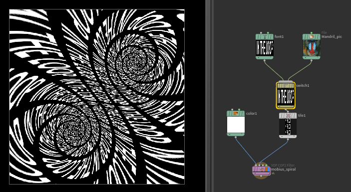
Mobius spiral
 Download hip: cops_mobius_spiral.hip
Made this a while ago after seeing this cool instagram post by Matt Taylor, forgot about it, someone on reddit just asked about getting that effect, here tis.
Like a lot of the examples on this page, it was mainly about finding an example on shadertoy I could barely understand, port it to vex, swear a lot, but eventually get there.
The shadertoy example I found (from https://www.shadertoy.com/view/XsGXDV ) is ultimately creating fancy uv's. Once you have that you can either directly feed that to a texture vop, or more usefully feed to a copinput vop, so you can distort other nodes in your cops graph.
Sample cops into lops
Not exactly cops, nor lops, but I figure if I need this trick again in future, I'll probably search the cops page first.
Say you have a texture, and you want to get its average pixel value, and store it as an attribute on your prim in lops.
Easy enough to take your image, scale it down to 3x3 pixels, the middle pixel should be what you need. How to get that to lops?
Make a lops wrangle, and use the texture or colormap call (as far as I can tell they're the same thing).
It just expect a path to a texture on disk, and a u and v value. Of course here you're referring to a texture within houdini, so you need that pesky op: prefix. Why not get the best of both lazy worlds by using a chs call so you have a parameter to lazily ctrl-c the node, then ctrl-v into the parameter, which will paste its path, then you can prefix 'op:' in code:
vex
string node = 'op:'+chs('copnode');
vector col = texture(node,ch('u'),ch('v'));
v@averageColor = col;
string node = 'op:'+chs('copnode');
vector col = texture(node,ch('u'),ch('v'));
v@averageColor = col;Set the u and v sliders to 0.5 so it samples the middle of the texture. Bam!