Appearance
Points and Verts and Prims
'Points points points, it's all Houdini users ever talk about' is what Jan Brady might say. If you're coming from a Maya background, you might wonder what the fuss is about. You might be extra puzzled when people talk about points vs primitives (prims for short), and even more puzzled when verticies (verts) are thrown into discussion too. What's the deal?
Short Answer - don't worry about it, just use points
There. Nearly everything in Houdini directly assumes you're working with points, just think in those terms, everything should work.
Oh, you wanna know more? Ok then...
A point
A point in Houdini is close to the mathematical definition of a point; it's a location in space, with no associated area or dimension or connectivity. At it's most basic, a point will store its position (@P).
If you're coming from other 3d packages, a point is equivalent to a particle; a standalone position in space. Maya particles can store colour as rgbPP, speed, velocity etc, a houdini point can also store colour, speed, velocity, as attributes, and even some attributes that don't make sense for a particle, like normal and scale. How can a dimensionless point have a normal? Or area?
The answer is that while a Houdini point derives from a mathematical point, we're not mathematicians damnit, we can do whatever the hell we want! For example, you have points representing a spray of water, and you want to render them. In a mathematically pure sense of a point, this makes no sense, they're infinitely small, invisible things. For Houdini and Mantra, they treat points as spheres with a radius of 0.1. If you have a @pscale attribute, it uses that as a radius instead. If you have @v, it will use that as a velocity vector, @Cd for colour etc....
Again relating back to maya, the particle comparison holds true. Yes particles are infinitely small, unless you have scalePP, and a dimensionless point can't possibly have colour, unless of course you've defined rgbPP, etc...
Creating points
There's many ways to create a point or points. The add sop is probably the easiest way, tick the toggle next to the first field, and there you go, a point:

The add sop can also be used to convert any poly, nurbs or curve back into points, by using the 'delete geometry but keep the points' toggle:

Some of the basic geometry sops (box, and grid for example) have an option to make points directly. For the others, just use the add 'delete geometry but keep the points' trick. Other sops that make unconnected points are scatter, generate points, points from volume, and probably several others I'm yet to discover...
Why points?
Maya folk usually bristle at all this, wondering what's wrong with vertices, isn't this all semantics? The answer is that by ensuring most of Houdini's tools are compatible with points, it means you're guaranteed everything works with everything. Maya has many low-level components (vertices, curve cv's, particles, lattice points, cluster handles, subdiv points etc), but that means that a tool designed to work with verts may not work with curve cvs or particles. In Houdini, if its a point, it can be manipulated as a point, regardless of how it was created.
Shadesails and verts and prims
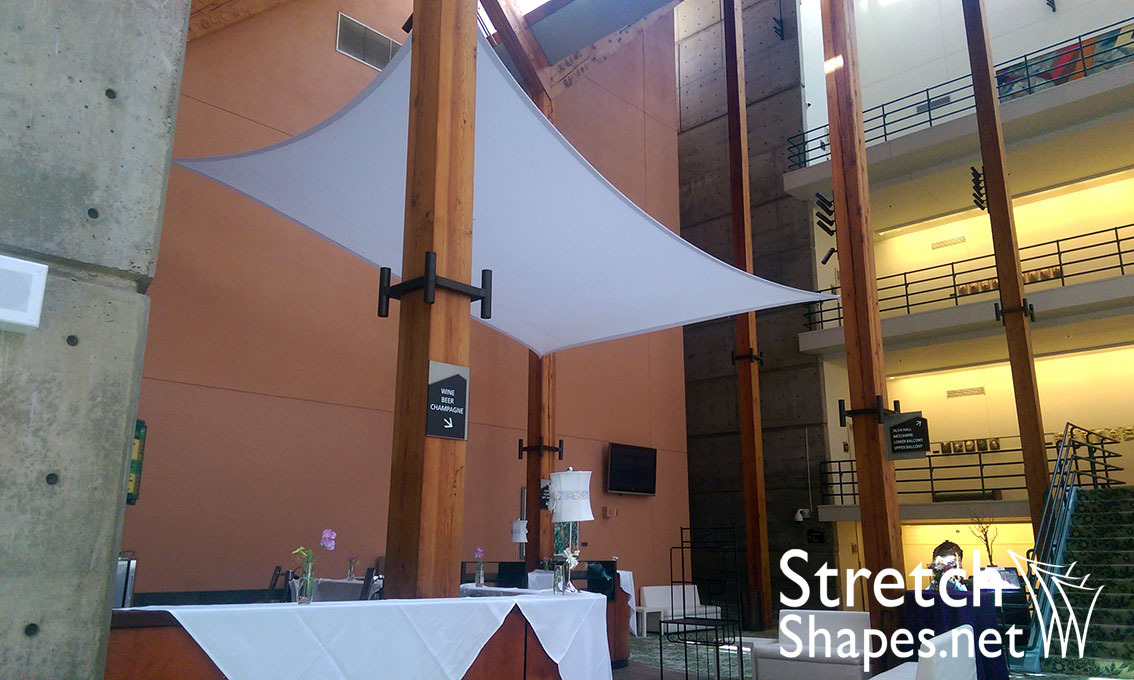
Have a look at the work done by this company: https://www.usa-shade.com/projects
To setup one of these sails, they have 4 hooks and some stretchy material. They take the material and attach it to each hook, forming a large flat shape:
Other sails have a single piece of material and many hooks:

While other setups have a complicated arrangement of hooks, and many pieces of material:
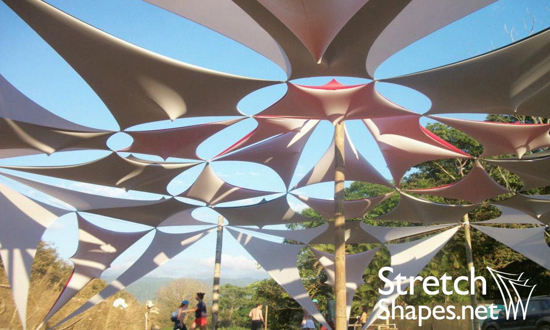
Here's a close up of one of the corners:

While those guys might call all those things 'pole-top', 'sail corner, 'sail', here's where this too-long analogy kicks back into houdini land, and you gasp in delight:

Now imagine you had this as a kit from Ikea. The instructions might be something like
- Erect poles 6 poles in 2 rows, 0 1 2 and 3 4 5
- Take sail 1, attach corner 0 to pole 0, corner 1 to pole 1, corner 2 to pole 3, corner 3 to pole 4.
- Take sail 2, attach corner 0 to pole 1, corner 1 to pole 2, corner 2 to pole 4, corner 3 to pole 5.
Here's that same setup, in Houdini, with points (red), verts (green), prims (yellow):

Note that while the outer corners have a 1-to-1 relationship (1 point controls 1 vertex), the inner points 1 and 4 each control 2 vertices. Once this relationship of points-to-verts-to-prims is setup, wherever the points move, the verts and prims of course move too.
It follows then that while you'll frequently manipulate points, and you'll occasionally work with prims (in the sailcloth analogy, you might paint one red and one blue), you rarely work directly with vertices. Their main purpose is to bind prims to points, once that is done, you can mostly ignore them.
Also note that you rarely do this sort of hand-wiring of points to verts to prims. Many tools within Houdini do this for you, but its useful to know what's going on under the hood.
So to formalise what we've stated so far:
Primitives are 'renderable things', like polygons. Vertices bind primitives to points. For polygon primitives, they represent the corners.
Visualising points and verts and prims
You don't use Houdini for long before you want to start keeping track of the numbers of your points/verts/prims. Because points and prims are the ones you usually modify, there's shortcuts to display their id's in the toolbar on the right of the viewport:

Vertex numbers can be displayed too, but you need to use the display menu for that; hit 'd' in the viewport, markers -> vertices -> numbers, 'd' again to close the window.

The geometry spreadsheet of course always lists these id's as the first column. Here you can also see how the point/vert/prim binding is done:

The first view is the points, which shows this shape has 6 points. The point number (@ptnum in vex) is down the left, and their position (@P) in the spreadsheet.
Jumping to the primitive view, this shows that there are 2 prims, 0 and 1 (@primnum in vex), with no attributes stored on them.
Finally looking in the vertex view, there's 8 vertices, but with an odd looking syntax, and a column that stores point numbers.
The "x:y | z" means "prim:vertex | point".
So 0:2 | 4 means prim 0, vertex 2, is connected to point 4.
![]()
Attributes and interpolation

Here I've assigned a random @Cd to the points of a grid (and overlaid a copy of the points over the grid so its easier to see). You can see that in this case, Houdini does an older game-engine style blend, interpolating @Cd across each prim, but also between the prims. If a point is shared by 4 prims, then the colour of that point is also shared and blended across those 4 prims.
What about if we set random colour on vertices?

We get interpolation across the prim, but only within each prim. Why? Well remember, vertices are the corners of the sails, so while they can interpolate within the prim, that colour isn't shared with other prims. If you could visualise the vertex colours it'd look like this:

Finally what if we set random colours on the prims? Well, there can't be any interpolation, so all you see is solid colour on each prim:

Normals
A similar thing happens for normals, which makes sense if you think about it for a bit, but is hard to grasp at first.

As the captions suggest, the first box has no normals, the next has point normals, then vertex normals, then face normals. Only the vertex normals one looks like its doing the right thing. Why?
The first one has no normals, but obviously the graphics card requires normals if its to do any lighting. As such it calculates normals on the fly per point, and interpolates them.
The second has point normals, but just like the colour example earlier, it gets interpolated between the verticies and across the faces, giving that recognisable early 3d game engine look.
The third has vertex normals. Remember, this means each corner of each prim can get its own value, so normals no longer interpolate, giving us the expected sharp-corner look.
The 4th with face normals is surprising. I would have expected it to do the right thing, but it shades totally black. If you orbit around the shape you can make it catch light on certain angles, but the entire box shades the same way. I suspect this is also graphics card driver related; it's doing its best to find some normals, doesn't know quite what to do with face normals, and does this strange thing. When rendered it doesn't do much better; it seems Mantra (Houdini's renderer) doesn't know or care to look for face normals, so just ignores it.
The moral here is; if you're working with polygons and expect sharp corners on things like boxes, use vertex normals.
Also, if you look on the box sop you'll see an 'add vertex normals' checkbox. For the longest time (maybe pre H14), you'd have to explicitly add normals with a facet sop or normal sop. New users would look at the default box and complain about the shading, more experienced houdini users would go through this whole discussion about explicitly adding normals, new users would get tense. Now there's a checkbox to keep everyone happy. 😃
Uvs
As it is for normals, so it is for uv's. More than likely you want seams and separated regions for uvs. If you store your uvs as point attributes, then they'll be interpolated between the points, meaning you'll always get wraparounds and ugliness.
If you store uv's as vertex attributes (which is what Houdini defaults to), they can be discontinuous, giving you the uv islands and borders you'd expect.
Here's the default pig, that has it's uv's stored as vertex attributes. If I use an attribpromote to move those uvs to point attributes, we start to see ugly stuff. Why?

Have a look in the uv view (space-5), you can see the problem. When uvs are at point level, they can't be discontinuous anymore, so all the uv islands become connected, uv madness.

So remember, if you want to control your uv seams, you need to apply uv's on verticies.
Edges and prims
We can work with points and prims, and sometimes verts, what about edges? Well, that's always been a sore point in Houdini. As we've seen, you only need to define prims via points and verticies, edges are a by-product of that. The truth of it is that if verts are kind of a second class citizen, then edges are definitely third class. Edges can't easily be manipulated, and you can't easily store attributes on them in the way you do with points/verts/prims.
"But Matt!" you cry, "Can't we do edge splits? Edge groups? Other edge things?"
Yes you can, but look closer, and it reveals the truth of it. Here I select one edge of a box and group it:

The edge doesn't have an id; instead it's selected by the points that define its corners (point 3 and point 7).
In practice it's not a big deal, usually this is enough to work with. Manipulating edges in vex can be a little tricky, as you're often working with them indirectly (there's a whole module in vex devoted to half-edges which I'm still trying to wrap my head around), but it's something to keep in mind.
Edges and polylines and curves
Here's a single prim, and next to it is a prim connected to an 'ends' sop, with 'close U' set to 'unroll'.

Notice the placement of the prim numbers? The second wireframe looking box has its primnums sitting directly on the edges. If you think of the prims as a soap bubble, the ends sop has essentially 'popped' that bubble per prim, reducing the prims back to just their edges.
This is a trick Maya doesn't have; edges don't have to belong to a prim, they can be a prim in their own right. Another way to think of it is as a curve constructed from polygon edges. They're super lightweight, easy to manipulate, and you end up using them all the time where in maya you'd have to use a special case of a 1-degree curve, and do whatever tricks needed to loft or extrude it back into polygons.
The box and grid primitives let you create themselves in just rows, or columns, or rows and columns of these polylines, thats what those other dropdowns represent on their parameter interface.
This is also the fastest way to get a renderable wireframe version of a shape; just put down an ends sop in unroll mode, you can now render it in mantra. You can even control the width of the line at each point by setting the @width parameter.

"But Matt!" you shout again, "Didn't you just say in the previous section that Houdini makes edges hard to work with?" Yes, yes I did. To clarify my statement, standalone edges, in a polywire/curve form are great. Regular polygons are great. Trying to access edges of connected regular polygons is where things get a bit tricky. Again, not impossible by any means, but you'll sometimes have to rethink a problem in context of only prims/points. Now stop interrupting.
Splitting prims
At some point you'll want to split shapes up per prim, or by some shared attribute, or shared vertex attribute. There's several ways of doing this.
The simplest way is with a fuse sop in unique mode. The fuse sop is actually 3 sops in one, fuse, unique, and grid snap. Swapping the UI tab to unique, bingo, the prims are separated.
In terms of what we've just discussed, what this does is split each shared point into a unique point per prim, and reconnects the vertices to those prims. Often there'll be no visual change, the clue will be in the geometry spreadsheet and middle mouse window (there'll be more points than you had previously), and if you do an operation that affects each point differently, you'll start to see the prims separate:

Another way is vertex split. You tell it what vertex attribute to split on, and it'll do its thing. Uvs are usually stored at the vertex level (remember, like normals, sometimes we want them to be unique, other times to be shared).
Handy helper sops are exploded view and the connectivity sop. A connectivity sop tries to identify islands of connected prims, and numbers each island with a unique @class attribute.
Exploded view also tries to identify islands, but rather than tag them, it just tries to translate them away from each other, like an exploded diagram from an engineering textbook (note that it works on packed primitives and voronoi fractures too, very useful!)
In this gif I split the pig by its uvs, use connectivity to identify the islands with a @class attrib, do a random colour from @class, and finally use an exploded view.

Create prims with add sop
Given some unconnected points, you can connect them back into a primitive with the add sop. Switch to the polygons tab, 'by group' subtab, and Houdini will wire up all the points in order of their ptnum's, as a polyline by default. Here I take a 2x2 grid (ie a single poly prim), convert it to points with an add sop in 'delete geometry but keep the points', then with a second add sop rebuild it into a polyline, then enabled 'closed' to make it into a full prim:

Ruh-roh. What happened? First the polyline is in a Z-shape, and the closed shape is all twisted and gross.
Well as I mentioned, without any hints, the add sop will just connect the points, sorted by @ptnum. If you look at the point numbers they do indeed form a z-shape. It was implied earlier, but here I'll state it explicity: when making prims from points, order is important. If way at the start of this tutorial the ikea instructions were wrong, you'd get twisted up polygons.
To fix, we can manually enter the point order in the group field. In practice, if you were making your own polygons or polylines, you'd be watching the order of your points carefully (things like the sort sop can be very useful here):

Store point order of prims via vex
I couldn't outline the previous problem and not provide a solution right?
The primpoints() function returns an array of points that create a prim, in the order of their winding. Eg, you need to know the points, in order, that make up prim 3, you could do
vex
int ptorder[] = primpoints(0,3)

// returns [14,16,17,18,15], which are the 5 points, in the order they're connected, to make up prim 3
int ptorder[] = primpoints(0,3)
// returns [14,16,17,18,15], which are the 5 points, in the order they're connected, to make up prim 3When you tell the add sop to create prims grouped by attribute, those points don't have to be grouped together in the spreadsheet, they just have to be in the correct order, the number of points in between them doesn't matter. Ie, if you have 20 prims you need to reconstruct, you can have all the first points listed together, then all the second, then all the third etc.
With that in mind, here's the workflow. First, make each point store the primid it's a part of, and its sort order within the prim. Sort all the points by sort order (this will put all the 0th points at the start, then all the 1st points, all the 2nd etc). Finally use an add to create the prims, using primid as the grouping attribute. The vex to store the primid and sort order looks like this:
vex
int ptorder[] = primpoints(0,@primnum);
i@sort = find(ptorder,@ptnum);
i@primid = @primnum;
int ptorder[] = primpoints(0,@primnum);
i@sort = find(ptorder,@ptnum);
i@primid = @primnum;Example scene: prim_store_point_order.hipnc
Create prims in vex
With the above understanding, creating prims from scratch in vex makes a lot more sense. Given the same 4 points above, here's how you'd create a polygon with a detail wrangle:
vex
int myprim = addprim(0,'poly');
addvertex(0,myprim,0);
addvertex(0,myprim,1);
addvertex(0,myprim,3);
addvertex(0,myprim,2);
int myprim = addprim(0,'poly');
addvertex(0,myprim,0);
addvertex(0,myprim,1);
addvertex(0,myprim,3);
addvertex(0,myprim,2);First we make an empty prim, and store its primnum as 'myprim', telling it if we want it to eventually be a solid shape ('poly'), or a polyline ('polyline'). Then we add vertices to it, which refer to the prim ('myprim', obviously), and the ptnum to add.
By now you should understand that unlike the physical example of sails and hooks, a prim is defined by its vertices, not the other way round. Ie, we can create an empty prim first, and its a 'ghost' prim essentially, a container ready to pop into existence as soon as we add 2 or more vertices to it.
Transforming prims
Another curious 'Ah! Eh? Hmm... ' moment that strikes is if you try and manipulate prims in vex. Clearly you can do it with a primitive sop, so there's an equivalent vex or vop function right?
Well, if you look in the geometry spreadsheet, you can see a distinct lack of any @P attributes on primitives. So if there's no @P for prims, how can we manipulate it? And how is the primitive sop doing it?
The primitive sop is pulling a trick on you. As you manipulate prims, its actually calculating temporary positions on the fly for each prim, and applying them to the associated points. As such, you need to do a similar trick in vops/vex.
If it's just translate and scale you're after, you can get the primitive center with 2 attrib promote sops. Promote P from point to prim in average mode, rename it as Pavg. Because you're getting the average of all the point positions per prim, you end up with the center. Append another attrib promote, and demote Pavg from prim to points, so now every point has its associated prim center point (this assumes you've split all your prims first!)
To scale, you use this to construct a vector towards the center of each prim, then add that to @P:
vex
vector scaler = v@Pavg - @P;
@P += scaler*ch('scale');
vector scaler = v@Pavg - @P;
@P += scaler*ch('scale');
Rotating is trickier, and involves calculating the axis you want to rotate around, then some mild dancing to make sure the rotation happens in the way you expect. I explain some methods for that in the main Houdini page, and the HoudiniVex page.
A lazy/clever way (depending on your point of view) is to pack the geometry so each prim becomes a packed prim. Manipulating rotation in that copy sop style way is generally easier, and so far hasn't been too much of a performance hit. As much as I'm loathe to say it, sometimes though just using a primitive sop is the faster and easier way. 😃
Other primitive types
While poly prims are by far the most used kind of primitive, houdini has a wide range of prims.
As mentioned right at the start, you can render points by themselves and they'll be represented as little spheres. Houdini and Mantra do this by creating a sphere primitive at runtime. This is a mathematically 'ideal' sphere, that gets its position from the point, and its radius from the point too (by looking for @pscale).
Houdini also supports circle primitives, poly lines, bezier curves, nurbs curves, nurbs surfaces, bilinear shapes, and at the interesting end, volumes and vdb. Even there, while a volume can be millions of voxels, ultimately its a single primitive, and its gets its position from the lowly point.
All praise points!