Appearance
Creating a 360 stereo VR lens shader
Houdini 15.5 ships with a VR camera, meaning this page is no longer relevant: http://www.sidefx.com/tutorials/vr-lens-camera/
This page is still mildy interesting in terms of explaining how a stereo vr camera works, and how to build custom camera shaders in Houdini. If any of that interests you, read on...
v05 of this thing, now does left and right eyes as over/under in one render! Useless but fun!
 Download scene, regular mode: oculus_shader_v04.hipnc
Download scene with over/under mode: oculus_shader_v05.hipnc
Background
We're rendering some cool stuff in mantra, would be cooler still if we could render oculus vr versions. But how?
At first glance you'd think 'Easy, Houdini does spherical panoramic cameras, render spherical panos from the left/right cameras, done'. Unfortunately, its not that simple.
Good stereo
Here's a stereo setup where the right camera is parented to the left, and we rotate 360 degrees:
 The right eye stays a fixed distance away from the left, and looking through the camera, you can see it always generates a consistent parallax as you'd expect.
Bad stereo
Now here's what you'd see if you generate a single spherical panorama on the first frame from each eye, then look around with a vr headset:
- Look north, things are good.
- Look west, there's no parallax! The left and right eyes are parallel in that direction.
- Look south, the eyes are flipped!
- Look east, no parallax
- Back to north, back to normal
This is no good.
Luckily a panorama/vr boffin recognised this problem several years ago, documented here: http://paulbourke.net/stereographics/stereopanoramic/
What we need is something like a slit-scan render; assuming the left eye is fixed, we need each vertical line of the right eye render to be translated perpendicular to the left eye to give parallax.
The solidangles guys have implemented this in arnold, and were nice enough to write it up and share source code, here: https://support.solidangle.com/display/mayatut/Creating+an+Oculus+Rift+Camera+Node
Time to try and do this in Houdini!
Lens shader
First thing to find out is how to define a different camera type in houdini. If you create a camera and go to the view tab, there's a drop down for the projection type, one option being 'lens shader'. This then enables the next parameter to let you choose a shader, cool.
 Next is to create the lens shader itself. This isn't documented very well within the sidefx docs, but there's a few hints on the odforce houdini forums. Forum member Eetu recently posted some stuff about baking renders into textures, part of his setup involved lens shaders, nice:
http://forums.odforce.net/topic/8471-eetus-lab/?p=132784
Unlike surface, displacement or light shaders, a lens shader isn't a specific shader type, rather its implemented as a generic cvex shader which expects certain inputs and outputs. The docs list them towards the bottom of this page: http://www.sidefx.com/docs/houdini14.0/nodes/obj/cam. The expected in/out values are:
\ `float x – X screen coordinate in the range -1 to 1`\ `float y – Y screen coordinate in the range -1 to 1`\ `float Time – Sample time`\ `float dofx – X depth of field sample value`\ `float dofy – Y depth of field sample value`\ `float aspect – Image aspect ratio (x/y)`\ export vector P – Ray origin in camera spaceexport vector I – Ray direction in camera spaceexport int valid – Whether the sample is valid for measuring
So that's great, but I still faced the problem of creating a pano camera shader from scratch. My maths isn't great, the arnold source was a little confusing, what I really needed was a working example. Luckily, Sidefx provide exactly that; the ASAD lens shader (ASAD = 'All Singing All Dancing') . Create one of these in a shopnet, r.click on it, choose 'type properties', go to the code tab, and there's working cvex code for a perspective camera, cylindrical, and the one we need, a spherical panorama. Sweet.
Create a stereo pano shader
Using the cvex pano code as a guide, it actually looked pretty simple: <code lang="cpp">
# setup float xa = -PI*x; float ya = (0.5*PI)*y; float sx = sin(xa); float cx = cos(xa); float sy = sin(ya); float cy = cos(ya); # output P = 0; I = set(cx*cy, sy, sx*cy);``</code>
Some googling and comparing notes between this and the arnold version revealed this is implementing a spherical co-ordinate system; theta (xa) is rotation around the y axis, phi (ya) is the up-down angle. Nice explanation and interactive javascript toy here: http://mathinsight.org/spherical_coordinates
By this time my brain was slooowly beginning to digest what was going on. The x and y inputs represent the film back, going from -1 to 1. The output P is the camera position, and output I (capital-i) is the angle of a ray fired from the camera. A regular perspective camera sweeps the camera ray from P out into the scene to form the view frustum. A pano camera traces out a sphere.
As seen in the example code above, P is assumed to be a fixed point. But for our case, we need that to shift. When I translated the above cvex code into a cvex vop equivalent (shopnet, tab menu, 'cvex shader builder'), I drove P from a promoted parameter, and slid the value around. Sure enough, the render view shifted as if I was translating the camera.
 Final step was to then shift the camera relative to the rotation around the Y axis. The arnold code revealed this is pretty simple:
``output->origin.x = -0.5*eyeSeparation*cos_theta*cos_phi;output->origin.z = -0.5*eyeSeparation*sin_theta*cos_phi;
Translating that to the cvex from earlier:
``P.x = -0.5 * eyeSeparation * cx * cy;P.z = -0.5 * eyeSeparation * sx * cy;
Translating that again into my vop setup, got what looks to be the correct result! Here's the finished network:

All that said, this is all still theory! Haven't actually tried this on a oculus headset yet... maybe today...
Create a WORKING stereo pano shader
So before even getting to fire up the rift, clever clogs Matt Ebb looked at the vop network above and said 'you sure you're meant to be driving the y property of P?', which of course I'm not. Further, upon stripping the scene back, while the warping was interesting, it was clearly wrong. Back to the drawing board.
Matt had made his own attempt, which also didn't do the right thing. Pressure was on.
Went back to the sidefx pano code, and this time skipped vops and went straight to inline vex, easier to adjust values this way. Drew a few diagrams, looked at the arnold code, looked at mine, in the end did my usual awesome coding technique for this trig stuff; swapped sines for cosines, negated, added offsets, threw PI here and there, until something started to look right. Eventually, got this:
 Great success!
The answer? Remove 'cy' from the P calculation, and negate the sine call for P.x to make the camera shift to the right. I suspect the cy was there to counter the distortion you'd get at the top and bottom of frame, but looks like its not needed. Here's the vex code:
\ `float pi = 3.1415;`\ `float xa = -pi*x;`\ `float ya = (0.5*pi)*y;`\ `float sx = sin(xa);`\ `float cx = cos(xa);`\ `float sy = sin(ya);`\ `float cy = cos(ya);`\ ` `\ `p.x = -ipd * -sx;`\ `p.z = -ipd * cx;`\ i = set(cx*cy, sy, sx*cy); $P = p;$I = i;
I'm sure there's a cleaner way to do this inline vex stuff, but hey, this looks like its working properly! Ok, now might be time to fire up the rift...
Have updated the scene link at the top of this page.
Testing in the rift
I have a DK1 lying around (thanks Alex Fry), suddenly occurred to me I had no idea how to view these stereo panos in the rift. Thought about creating something in Unreal Editor, but thought 'nah, too slow, too much work, must be something pre-existing'. Hours later, several shouting matches with oculus runtimes, crashy bleeding edge webvr browsers, and an interesting-but-obtuse web pano suite called krpano tools, I got it working. So yes, UE4 would have been faster. Oh well, next time.
Still, it works!
- webvr (I used the chrome version): http://webvr.info/
- krpano: http://krpano.com/forum/wbb/index.php?page=Thread&postID=58228#post58228
 Oh, here's the left and right images I tested with:
Render left and right eyes simultaneously in over/under
Found 2 much easier ways to view these things, whirligig and liveViewRift. Both expect the left and right eyes to be stored in the one image, eithes as left/right or over/under. With a bit of hacking its easy enough to make this render directly out of mantra; the y coordinates go from -1 to 1, so you can run different spherical coordinates if y < 0:
\ `float pi = 3.14159265359;`\ `// point north in center`\ `//float xa = -pi*(x+0.5);`\ `// rift prefers north where it is. *shrug*`\ `float xa = -pi*x;`\ `float ya;`\ if (y < 0) { ya = (0.5*pi)*(y*2-1);} else { ya = (0.5*pi)*(y*2+1);}\ `float sx = sin(xa);`\ `float cx = cos(xa);`\ `float sy = sin(ya);`\ `float cy = cos(ya);`\ if (y < 0) { p.x = ipd * -sx; p.z = ipd * cx; i = set(cx*cy, -sy, sx*cy); } else { i = set(cx*cy, -sy, sx*cy);} $P = p;$I = i;
You wouldn't want to use this for final renders (compers would get all huffy), but handy for rapid prototyping.
Correction for Gear VR cubemap rendering
 Pole distortion with and without factor 'cy' in position offsets.
The removal of factor 'cy' from position offsets in step 6 introduces distortion artifacts at poles. The result is incorrect for Gear VR stereoscopic panoramas, and presumably for other uses as well. The factor 'cy' reduces eye separation towards the poles, removing the artifacts in the process. After this little tweak the vex code looks like this:
\ `float pi = 3.1415926;`\ `float xa = -pi * x;`\ `float ya = (0.5 * pi) * y;`\ `float sx = sin(xa);`\ `float cx = cos(xa);`\ `float sy = sin(ya);`\ `float cy = cos(ya);`\ p.x = -ipd * -sx * cy;p.z = -ipd * cx * cy;\ `i = set(cx * cy, sy, sx * cy);`\ $P = p;$I = i;
Viewing the results with Gear VR
The stock Oculus 360 Photos application expects a 1536 x 1536 px per face cubemap with all faces stacked vertically on top of each other. 6 faces for monoscopic image (1536 x 9216 px) and 12 faces for stereoscopic image (1536 x 18432 px). For the stereoscopic image right eye cubemap is on top, left eye cubemap on bottom.
Cubemap face order:
- X+ Right
- X- Left
- Y+ Top
- Y- Bottom
- Z+ Forward
- Z- Backward
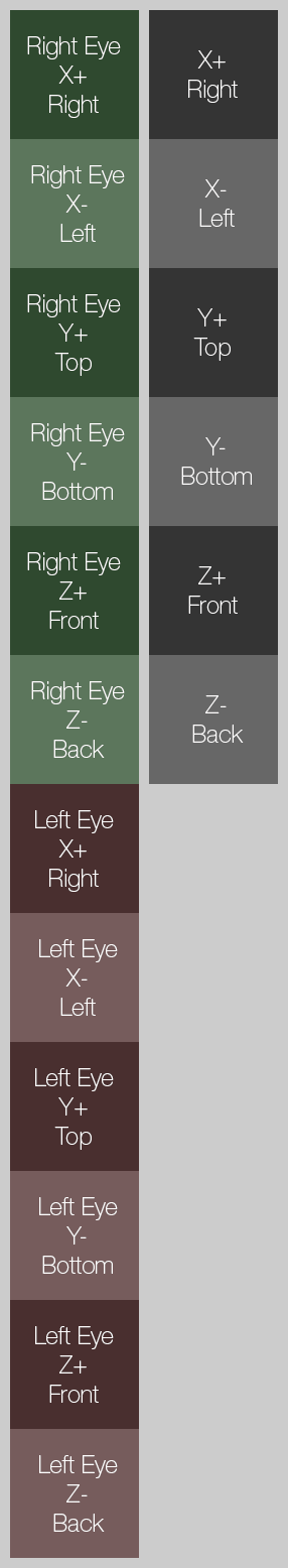 Cubemap layouts for stereoscopic and monoscopic panoramic pictures.
The equirectangular renders can be converted to cubemaps with one of the many panorama applications available, or you could extend the lens shader to deal with it. After you have constructed the cubemap you can follow the official instructions on how to view it with your Gear VR.
Next steps
I've wanted to create my own cg lenses for ages, got a few ideas... HoudiniLensShaders