Appearance
Vex Section 1
New to Vex? You might want to read JoyOfVex first.
Still here? Ok then...
So you've pushed past hscript, ignored python for now, and seen the awesomeness of vops. You'll also probably start to get curious as to why there's at least 4 different ways to define point attributes, all with various idosyncrasies. Time to sweep all that away with Vex, specifically with the Wrangle Sop.
Wrangle Sops let you write little bits of Vex code, and come with a few UI niceties to make them quick and efficient to use. They come in various flavours (point, prim, detail, attribute), they're all the same thing, just with the 'what do i operate on' menu switched to point/prim/detail.
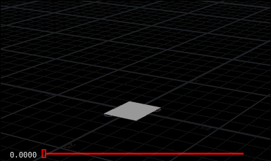
Best way to get into vex and wrangle nodes is to put down a 40x40 grid, append a point wrangle, and follow along.
These section breaks don't really mean anything, I just had to fold up the chapters so the table of contents on the left there didn't overflow off the bottom of the browser window!
Create a new attribute
You want to define a new point float attribute 'foo'? Just type
vex
@foo;@foo;Hit ctrl-enter, look in the geometry spreadsheet, there you go, float attribute. The @ tells houdini that you want this to be an attribute, the default type is float.
You want it initialised?
vex
@foo=1;@foo=1;You want a vector attribute? Prepend 'v' before the '@'. To initialise, use curly braces if its just numbers, or use set() if you're doing something with functions or other attributes:
vex
v@myvector={1,0,3};
v@other=set(0, @P.x, 1);v@myvector={1,0,3};
v@other=set(0, @P.x, 1);You can set the attribute type using the appropriate prefix. The default is float, so you rarely need the f@ prefix.
vex
// floats and integers
f@myfloat = 12.234; // float
i@myint = 5; // integer

// vectors
u@myvector2 = {0.6, 0.5}; // vector2 (2 floats)
v@myvector = {1,2,3}; // vector (3 floats)
p@myquat = {0,0,0,1}; // quaternion / vector4 / 4 floats

// matricies
2@mymatrix2 = {1,2,3,4}; // matrix2 (2x2 floats)
3@mymatrix3 = {1,2,3,4,5,6,7,8,9}; // matrix3 (3x3 floats)
4@mymatrix4 = {1,2,3,4,5,6,7,8,9,10,11,12,13,14,15,16}; // matrix (4x4 floats)

// strings and dictionaries
s@mystring = 'a string'; // string
d@mydict = {}; // dict, can only instantiate as empty type
d@mydict['key'] = 'value'; // can set values once instantiated
// floats and integers
f@myfloat = 12.234; // float
i@myint = 5; // integer
// vectors
u@myvector2 = {0.6, 0.5}; // vector2 (2 floats)
v@myvector = {1,2,3}; // vector (3 floats)
p@myquat = {0,0,0,1}; // quaternion / vector4 / 4 floats
// matricies
2@mymatrix2 = {1,2,3,4}; // matrix2 (2x2 floats)
3@mymatrix3 = {1,2,3,4,5,6,7,8,9}; // matrix3 (3x3 floats)
4@mymatrix4 = {1,2,3,4,5,6,7,8,9,10,11,12,13,14,15,16}; // matrix (4x4 floats)
// strings and dictionaries
s@mystring = 'a string'; // string
d@mydict = {}; // dict, can only instantiate as empty type
d@mydict['key'] = 'value'; // can set values once instantiatedThe sidefx documentation is here: https://www.sidefx.com/docs/houdini/vex/snippets.html#attributes
Get existing attribute values
You want myvector to get its values from the point position?
vex
v@myvector=@P;v@myvector=@P;The @ symbol is used to get attributes as well as set them. All the attributes you see in the geometry spreadsheet, you can access them by sticking @ in front of their name.
You want it 1.5 times N?
vex
v@myvector=@N*1.5;v@myvector=@N*1.5;To access an individual attribute of a vector or colour, use @attribute.channel. Eg to get just the y value of each point and divide in half:
vex
@foo=@P.y / 2;@foo=@P.y / 2;To set it is similar. Eg to set the red channel of each point to the sine of double the x position:
vex
@Cd.r = sin( @P.x * 2 );@Cd.r = sin( @P.x * 2 );Vector attributes like Cd or P let you refer to components in several ways, use whatever is convenient. The component can be r/g/b, x/y/z, [0]/[1]/[2].
vex
// These all do the same thing, set the first component of the vector:
@Cd.r = 1;
@Cd.x = 1;
@Cd[0] = 1;

// As are these, all setting the third component:

@P.z = 6;
@P.b = 6;
@P[2] = 6;
// These all do the same thing, set the first component of the vector:
@Cd.r = 1;
@Cd.x = 1;
@Cd[0] = 1;
// As are these, all setting the third component:
@P.z = 6;
@P.b = 6;
@P[2] = 6;Implicit vs explicit attribute type
Note that wrangles implicitly know certain common attribute types (@P, @Cd, @N, @v, @orient, @id, @name, several others), but if you have your own attributes, Houdini will assume its a float unless told otherwise, easy mistake to make.
To ensure Houdini does the right thing, prepend the type. Eg, you've set @mycolour as a vector, and try to use it in a wrangle:
vex
// BAD
@Cd = @mycolour; // This will treat it as a float and only read the first value (ie, just the red channel of @mycolour)

// GOOD
@Cd = v@mycolour; // Explicitly tells the wrangle that its a vector.
// BAD
@Cd = @mycolour; // This will treat it as a float and only read the first value (ie, just the red channel of @mycolour)
// GOOD
@Cd = v@mycolour; // Explicitly tells the wrangle that its a vector.I always forget to do this, shout at my wrangles for a bit, then finally remember to stick 'v' in front of my attribute names. No doubt you'll do the same. 😃
Parallel processing, part 1
If you've used other programming languages, you might be thinking 'Ok, but how does Vex know which point to process? How do I iterate through the geometry? There's too much voodoo here!'
The answer is that Vex is implicitly working in parallel. You can think of the code we've done so far as working on a single point, so something like
@Cd = @P;
Is setting the colour of a point based on its position. When you have lots of points, Vex runs that same code on all the points in parallel, substituting the values for Cd and P for each point automatically. You don't have to sweat the details (for now), just understand that's what's going on. This affects how you might approach certain problems, which I'll come back to later.
Create UI controls
Say you have this:
vex
@Cd.r = sin( @P.x * 5 );@Cd.r = sin( @P.x * 5 );But you want to change 5 to another number. You can keep altering the code with different numbers, or replace 5 with ch('scale') :
vex
@Cd.r = sin( @P.x * ch('scale') );@Cd.r = sin( @P.x * ch('scale') );ch() tells Houdini to look for a channel, which is what Houdini calls a UI component, usually a slider. Hit the little plug icon to the right of the text editor, Houdini scans the vex code, realises you've referred to a channel that doesn't exist yet, and makes a channel at the bottom of the wrangle UI named 'scale'. Start sliding it around, you'll see the colours update.
There's several channel types you can use. ch() and chf() both create a float channel. For the others:
vex
// An int channel
i@myint = chi('myint');

// A vector channel
v@myvector = chv('awesome');

// A ramp channel
f@foo = chramp('myramp',@P.x);
// An int channel
i@myint = chi('myint');
// A vector channel
v@myvector = chv('awesome');
// A ramp channel
f@foo = chramp('myramp',@P.x);The last one is really handy, in one line you get to read one value (@P.x), remap it via the UI ramp widget, and feed that to @foo. I end up using loads of these all through my setups. It assumes the incoming values are in the 0-1 range, you often have to fit the values before feeding to the ramp. The fit function goes fit( value, oldmin, oldmax, newmin, newmax). Eg, remap X between -0.5 and 6, then use a ramp to feed those values into the red channel:
vex
float tmp = fit(@P.x, -0.5,6,0,1);
@Cd.r = chramp('myramp',tmp);
float tmp = fit(@P.x, -0.5,6,0,1);
@Cd.r = chramp('myramp',tmp);But why stop there? Define the start and end points with UI sliders!
vex
float min = ch('min');
float max = ch('max');
float tmp = fit(@P.x, min,max,0,1);
@Cd = 0;  // lazy way to reset the colour to black before the next step
@Cd.r = chramp('myramp',tmp);
float min = ch('min');
float max = ch('max');
float tmp = fit(@P.x, min,max,0,1);
@Cd = 0; // lazy way to reset the colour to black before the next step
@Cd.r = chramp('myramp',tmp);Customise the UI elements
The plug button is a convenience function, it just scans for any channel references, and creates the default type, with a default value. Once the channel is made, you can right.click on the wrangle node and choose 'edit parameter interface' (or use the gear menu from the parameter panel), and change float ranges, the default value, the labels, whatever you want.
A handy thing I often do is to convert the default vector channel to a colour channel. I'll make as many vector channels as I need in vex, eg:
vex
v@colour1 = chv('col1');
v@colour2 = chv('col2');
v@colour3 = chv('col3');
v@colour4 = chv('col4');
v@colour1 = chv('col1');
v@colour2 = chv('col2');
v@colour3 = chv('col3');
v@colour4 = chv('col4');Then I'll hit the plug button, edit the parameter interface, shift-select all the channels I made, and change the type field to 'color', and to be extra saucy, change 'show color as' to 'hsv sliders'. Most handy.
Common functions
These appear in 99% of my vex wrangles:
- fit() - take a number between 2 values, fit it between 2 other values, usually 0-1. Eg, remap @u from range -5,20 to 0-1: foo = fit(@u, -5, 20, 0, 1);
- rand() - generate a random number between 0 and 1. Usually feed it the point id, so each point gets a random number: foo = rand(@ptnum);
- sin(), cos() - as you'd expect, but in radians.
- radians() - convert a number from degrees to radians: foo = radians(90);
- length() - measure the length of a vector. Eg, measure the distance of a point from the origin: dist = length(@P);
- distance() - measure the distance between two points: dist = distance(@P, v@mypoint);
Built-in attributes
There's a few built in variables you can use, easiest way to see them is to put down a point vop, and look at the global params. Here's the more common ones:
- @ptnum - the point id
- @numpt - total number of points
- @Time - current time, in seconds
- @Frame - current frame
- @primnum - the primitive id
- @numprim - the total number of primitives
Example: Random delete points by threshold
After Matt Ebb showed me this, I use it a million times a day. Scatter some points, put down a wrangle with this:
vex
if ( rand(@ptnum) > ch('threshold') ) {
   removepoint(0,@ptnum);
}
if ( rand(@ptnum) > ch('threshold') ) {
removepoint(0,@ptnum);
}Use the plug button to create the threshold slider, now slide it up between 0 and 1, you'll see points get randomly deleted. What's going on:
- rand(@ptnum) -- each point gets a random number between 0 and 1 based on its id
- > ch('threshold') -- compare that random number to the threshold slider. If it's greater than the threshold...
- removepoint(0,@ptnum) -- ...delete the point. 0 means the first input, ie whatever you've connected into this wrangle, and @ptnum is the reference to the point.
Example: Wave deformer
A classic. Got your 40x40 grid ready? Good.
We'll make concentric sine waves that radiate from the center. That means we'll need to measure the distance of each point to the origin:
vex
@d = length(@P);@d = length(@P);We'll feed that to a sin(), and use that to directly set the y-position of each point:
vex
@P.y = sin(@d);@P.y = sin(@d);Good, but the waves are too big for our default grid. Lets multiply @d by some factor, that'll give us more waves. Change the previous line to read:
vex
@P.y = sin(@d*4);@P.y = sin(@d*4);Ok, but lets make that driven by a slider instead:
vex
@P.y = sin(@d*ch('scale'));@P.y = sin(@d*ch('scale'));Hit the plug button, play with the slider (you can push the slider past 1), see the waves move around.
To make the waves animate, add time to the inner term.
vex
@P.y = sin(@d*ch('scale')+@Time);@P.y = sin(@d*ch('scale')+@Time);wait, they're moving towards the center. Lets make it negative time:
vex
@P.y = sin(@d*ch('scale')-@Time);@P.y = sin(@d*ch('scale')-@Time);Or better, control it by a slider so you can drive the speed:
vex
@P.y = sin(@d*ch('scale')+(ch('speed')*@Time));@P.y = sin(@d*ch('scale')+(ch('speed')*@Time));That's messy, lets tidy up the whole thing. Nice thing about wrangles is you can split across multiple lines for readability:
vex
@d = length(@P);
@d *= ch('scale');
@speed = @Time*ch('speed');
@P.y = sin(@d+@speed);
@d = length(@P);
@d *= ch('scale');
@speed = @Time*ch('speed');
@P.y = sin(@d+@speed);Lets add 2 more things, a control for the maximum height, and a distance based falloff.
Height is easy, whatever the final result is, we'll multiply it by a channel reference; if its 1 it'll be unchanged, 0 will cancel out, other numbers will scale appropriately:
vex
@P.y *= ch('height');@P.y *= ch('height');And finally a ramp to control the falloff. A ramp widget expects a variable in the 0-1 range, so the first thing we'll do is take the distance variable, and use fit() to map it between 1 and 0 (note we go 1 0, not 0 1; we want the center to be of maximum height). The start and end points will be controlled by channels:
vex
@falloff = fit(@d, ch('start') , ch('end') , 1,0);@falloff = fit(@d, ch('start') , ch('end') , 1,0);A ramp channel expects a name and a variable, the variable will be remapped through the ramp curve. We'll take the result and directly multiply it against P.y:
vex
@P.y *= chramp('falloff', @falloff);@P.y *= chramp('falloff', @falloff);A minor annoyance here is that I expected the start and end to be in worldspace units, but the 'end' channel was a large number. I realised that's because we'd already multiplied d by the scaling channel to control the number of waves. A quick reshuffle of the code fixed that, here's the end result:
vex
@d = length(@P);
@speed = @Time * ch('speed');
@falloff = fit(@d, ch('start'), ch('end'),1,0);

@P.y = sin(@d*ch('scale')+@speed);
@P.y *= ch('height');
@P.y *= chramp('falloff', @falloff);
@d = length(@P);
@speed = @Time * ch('speed');
@falloff = fit(@d, ch('start'), ch('end'),1,0);
@P.y = sin(@d*ch('scale')+@speed);
@P.y *= ch('height');
@P.y *= chramp('falloff', @falloff);Attributes vs variables
The examples given above all use the @ syntax to get and set attributes on points. If you have more than a few wrangles, or if you don't need those attributes outside the wrangle, the geometry spreadsheet starts getting very messy, and all that extra point data takes up memory, especially if you have complex scenes.
Instead, you can create variables that only exist within the wrangle. The syntax is similar to other c-style languages; define the type with a full word, and don't use a prefix on the variable:
vex
float foo;
vector bar = {0,0,0};
matrix m;

foo = 8;
bar.x += foo;
float foo;
vector bar = {0,0,0};
matrix m;
foo = 8;
bar.x += foo;Point attributes and vex variables live in seperate worlds, so you can have one of each with the same name, and they happily co-exist. I tend to avoid this in practice, easy to add an @ where you didn't mean, or remove one where you need it, and break things:
vex
float dist = length(@P);  // a local vex variable that only exists within this wrangle

@dist = dist;  // create a new point attribute, @dist, and assign the local variable 'dist' to it. Worlds collide!
float dist = length(@P); // a local vex variable that only exists within this wrangle
@dist = dist; // create a new point attribute, @dist, and assign the local variable 'dist' to it. Worlds collide!Rewriting the previous example to use variables, and do the formal thing of declaring variables first so its clear to see whats going on:
vex
float d;
float speed;
float falloff;

d = length(@P);
speed = @Time * ch('speed');
falloff = fit(d, ch('start'), ch('end'),1,0);

@P.y = sin(d*ch('scale')+speed);
@P.y *= ch('height');
@P.y *= chramp('falloff', falloff);
float d;
float speed;
float falloff;
d = length(@P);
speed = @Time * ch('speed');
falloff = fit(d, ch('start'), ch('end'),1,0);
@P.y = sin(d*ch('scale')+speed);
@P.y *= ch('height');
@P.y *= chramp('falloff', falloff);Example: Rotation
This chapter was a request from Patreon supporter jon3de, thanks Jonathan!
Rotate a single point with sin and cos
Say you have a single point at the origin, and you want to animate it going round in a circle. Sin() will give you a smooth wave between 0 and 1. Cos() gives the same, but offset by half a wavelength. If you drive x by sin, and y by cos, and make the input to both @Time, the point will move in a circle:
vex
@P.x = sin(@Time);
@P.y = cos(@Time);@P.x = sin(@Time);
@P.y = cos(@Time);What if we have a box? Maybe we can add this to the existing @P, and it will rotate?
vex
@P.x += sin(@Time);
@P.y += cos(@Time);@P.x += sin(@Time);
@P.y += cos(@Time);Not quite. It translates the box in a circle, but it doesn't rotate.
Rotate geometry with sin and cos
The problem is all the points are getting an identical rotation value. What we need to do is get the offset of each point, but as a rotation offset. Casting your mind back to high school maths, you can use tan(), if given the x and y, will return you an angle. If you think about it, each point is a time offset away from the other points, so lets add this to @Time and see what happens:
vex
float angle = atan(@P.x, @P.y);

@P.x += sin(@Time+angle);
@P.y += cos(@Time+angle);
float angle = atan(@P.x, @P.y);
@P.x += sin(@Time+angle);
@P.y += cos(@Time+angle);It's rotating, but doing a weird scale thing as it rotates. We probably want to set the position rather than add to the existing position:
vex
float angle = atan(@P.x, @P.y);

@P.x = sin(@Time+angle);
@P.y = cos(@Time+angle);
float angle = atan(@P.x, @P.y);
@P.x = sin(@Time+angle);
@P.y = cos(@Time+angle);It's close, but if you compare to the original box, it's scaled slightly different. What's happening is we need to also get the radius (ie, the distance the point is from the origin), and multiply that by the rotation to get the correctly scaled value:
vex
float angle = atan(@P.x, @P.y);
float r = length(@P);

@P.x = sin(@Time+angle)*r;
@P.y = cos(@Time+angle)*r;
float angle = atan(@P.x, @P.y);
float r = length(@P);
@P.x = sin(@Time+angle)*r;
@P.y = cos(@Time+angle)*r;Try it on the pig. Uh oh, something funky's going on, his snout has ballooned out and is all strange. The problem is the radius; we're measuring the distance in 3d space, but all we need is the direct radius to the axis of rotation (ie, the z axis). If we measure the length just using @P.x and P.y, it should fix it:
vex
float angle = atan(@P.x, @P.y);
float r = length(set(@P.x, @P.y));

@P.x = sin(@Time+angle)*r;
@P.y = cos(@Time+angle)*r;
float angle = atan(@P.x, @P.y);
float r = length(set(@P.x, @P.y));
@P.x = sin(@Time+angle)*r;
@P.y = cos(@Time+angle)*r;Done! What we've done here is convert our regular coordinates to polar coordinates (angle and r), then back again. Just looking at the polar coordinates by itself is pretty interesting:
vex
float angle = atan(@P.x, @P.y);
float r = length(set(@P.x, @P.y));

@P.x = angle;
@P.y = r;
@P.z = 0;
float angle = atan(@P.x, @P.y);
float r = length(set(@P.x, @P.y));
@P.x = angle;
@P.y = r;
@P.z = 0;If you look at that in wireframe, you can see that it looks like a cylindrical uv projection, because that's exactly what it is. The weird stretching is because when doing uv's you'd pick a seam point to split edges on, we haven't bothered to do that here.
Going back to the original rotation, if we take out the time attribute and replace it with a channel, we get a simple rotation tool:
vex
float angle = atan(@P.x, @P.y);
float r = length(set(@P.x, @P.y));
float amount = ch('amount');

@P.x = sin(amount+angle)*r;
@P.y = cos(amount+angle)*r;
float angle = atan(@P.x, @P.y);
float r = length(set(@P.x, @P.y));
float amount = ch('amount');
@P.x = sin(amount+angle)*r;
@P.y = cos(amount+angle)*r;Click the button to get the slider, slide away. You'll note that an amount of '1' rotates by about 30 degrees, which doesn't make sense. Well it does; sin/cos/atan all work in radians. If we're assuming the slider is degrees, you need to convert it to radians too:
vex
float angle = atan(@P.x, @P.y);
float r = length(set(@P.x, @P.y));
float amount = radians(ch('amount'));

@P.x = sin(amount+angle)*r;
@P.y = cos(amount+angle)*r;
float angle = atan(@P.x, @P.y);
float r = length(set(@P.x, @P.y));
float amount = radians(ch('amount'));
@P.x = sin(amount+angle)*r;
@P.y = cos(amount+angle)*r;Rotate into a twirl or spiral
Now you can experiment with silly things. Rather than rotating all points equally, what if you scaled it based on radius? Ie, points near the origin won't get rotated, points far away get rotated a lot. You get a twirl. If you just add 'r' you get a subtle twirl, so I've added another slider to scale the twirl effect:
vex
float angle = atan(@P.x, @P.y);
float r = length(set(@P.x, @P.y));
float amount = radians(ch('amount'));
float twirl = r*ch('twirl');

@P.x = sin(amount+angle+twirl)*r;
@P.y = cos(amount+angle+twirl)*r;
float angle = atan(@P.x, @P.y);
float r = length(set(@P.x, @P.y));
float amount = radians(ch('amount'));
float twirl = r*ch('twirl');
@P.x = sin(amount+angle+twirl)*r;
@P.y = cos(amount+angle+twirl)*r;Rotate with a matrix
That all works, but gets a little tricky if you want to do rotations that aren't perfectly aligned on the x/y/z axis. Another way to do rotation is with a matrix. You're using Houdini, so you're probably aware of matricies, but you're reading this tutorial, so like me you'd probably panic if someone asked you to apply a matrix transformation to some geometry. Well, don't worry, it's easier than it sounds. Here's the steps:
- Create a matrix
- Rotate the matrix
- Apply the matrix to our geometry
The last step is simple, to apply a matrix to a point, you just multiply it.
The other two things are easier to explain in code: So what we need is a matrix, and a way to rotate it. Amazingly, the function is called rotate. Here's how it all works:
vex
// create a matrix
matrix3 m = ident();

// rotate the matrix
vector axis = {0,0,1};
float angle = radians(ch('amount'));

rotate(m, angle, axis);

// apply the rotation
@P *= m;
// create a matrix
matrix3 m = ident();
// rotate the matrix
vector axis = {0,0,1};
float angle = radians(ch('amount'));
rotate(m, angle, axis);
// apply the rotation
@P *= m;So we create an empty matrix (ie, rotates are 0 0 0, scale is 1 1 1). We then define the axis to rotate along, and the amount to rotate. Then we call rotate, which will modify the matrix m directly. Finally we multiply it against @P to apply the rotation per point.
Similar to above, you can do twirl effects by multiplying angle by the distance to to the axis, and scaling it to control the strength of the effect:
vex
vector axis = {0,0,1};
float angle = radians(ch('amount'));
angle *= ch('twirl')*length(set(@P.x, @P.y));
matrix3 m = ident();

rotate(m, angle, axis);

@P *= m;
vector axis = {0,0,1};
float angle = radians(ch('amount'));
angle *= ch('twirl')*length(set(@P.x, @P.y));
matrix3 m = ident();
rotate(m, angle, axis);
@P *= m;Because we work with an axis, that can be anything we want. A random vector, N, some arbitrary other thing, doesn't matter.
A nice bonus of using matrices to do rotation, is that it maps easily into @orient. When using the copy sop or instancing, if they find an @orient attribute, each copied shape will be rotated. @orient is a quaternion, a 4 value vector which is not easily manipulated by humans, but you can convert a matrix to a quaternion easily with quaternion().
Here's what you might do to get random rotations on every point, that you would then feed to a copy sop:
vex
vector axis = vector(rand(@ptnum));
float angle = radians(ch('amount'));
matrix3 m = ident();

rotate(m, angle, axis);
@orient = quaternion(m);
vector axis = vector(rand(@ptnum));
float angle = radians(ch('amount'));
matrix3 m = ident();
rotate(m, angle, axis);
@orient = quaternion(m);Rotate prims around an edge
Based on what we know so far, it shouldn't be too hard to rotate primitives around an edge. (We'll assume we have a single triangle or quad for now). You treat the edge as your rotation axis, and rotate as shown earlier. If you remember your vector maths, to get the vector between 2 points, you subtract them. So assuming the edge we want is between point 0 and point 1, we could do this:
vex
vector p0 = point(0,'P',0);
vector p1 = point(0,'P',1);

vector axis = p0-p1;
vector p0 = point(0,'P',0);
vector p1 = point(0,'P',1);
vector axis = p0-p1;And use it to create a quaternion orient as we've seen already:
vex
float angle = ch('angle');
matrix3 rotm = ident();
rotate(rotm, angle, axis);
vector4 orient = quaternion(rotm);
float angle = ch('angle');
matrix3 rotm = ident();
rotate(rotm, angle, axis);
vector4 orient = quaternion(rotm);Now if you were to apply this directly to the geometry, it would rotate, but it would rotate centred on the origin, which is wrong. The rotation has to be centred at the midpoint of the edge. Again casting your mind back to high school, you can get the midpoint of 2 points by adding, then divide by 2:
vex
// get midpoint of edge
vector pivot = (p0+p1)/2;// get midpoint of edge
vector pivot = (p0+p1)/2;From here, there's probably a few ways in vex to make this do what we need, in my case I use instance(). This is a vex call that constructs a transformation matrix similar to what a copy sop creates per copy. This means you can feed it position, orient, pivot etc, and it does what we want. As such, we'll construct an orient quaternion first, use that as one of the inputs to instance() along with our pivot, and then use this to move our point:
vex
// create a transform matrix using orient and pivot, and other default values
vector N = 0; // not important cos we're using orient
vector scale = 1; // ie, leave the scale as-is
vector postrotation = 0; // also not important, we don't need extra rotation on our orient
matrix m = instance(pivot, N, scale, postrotation, orient, pivot);
// move the point!
@P *= m;// create a transform matrix using orient and pivot, and other default values
vector N = 0; // not important cos we're using orient
vector scale = 1; // ie, leave the scale as-is
vector postrotation = 0; // also not important, we don't need extra rotation on our orient
matrix m = instance(pivot, N, scale, postrotation, orient, pivot);
// move the point!
@P *= m;Simple! Well, if we have many prims in a shape, then there's a few more book-keeping things to do. First, the prims will have to be split apart, so use a fuse sop in unique mode to do this. Then, to get the 0 and 1 point per prim, you can use primpoints(), which will return an array of the points in a primitive, in order. You can just grab the 0 and 1 entries of that array:
vex
int points[] = primpoints(0,@primnum); // list of points in prim
// get @P of first and second point
vector p0 = point(0,'P',points[0]);
vector p1 = point(0,'P',points[1]);int points[] = primpoints(0,@primnum); // list of points in prim
// get @P of first and second point
vector p0 = point(0,'P',points[0]);
vector p1 = point(0,'P',points[1]);Here's the full thing, for completeness:
vex
int points[] = primpoints(0,@primnum); // list of points in prim
// get @P of first and second point
vector p0 = point(0,'P',points[0]);
vector p1 = point(0,'P',points[1]);
vector axis = p0-p1;
float angle = ch('angle');
matrix3 rotm = ident();
rotate(rotm, angle, axis);
vector4 orient = quaternion(rotm);
// get midpoint of edge
vector pivot = (p0+p1)/2;
// create a transform matrix using orient and pivot, and other default values
vector N = 0; // not important cos we're using orient
vector scale = 1; // ie, leave the scale as-is
vector postrotation = 0; // also not important, we don't need extra rotation on our orient
matrix m = instance(pivot, N, scale, postrotation, orient, pivot);
// move the point!
@P *= m;int points[] = primpoints(0,@primnum); // list of points in prim
// get @P of first and second point
vector p0 = point(0,'P',points[0]);
vector p1 = point(0,'P',points[1]);
vector axis = p0-p1;
float angle = ch('angle');
matrix3 rotm = ident();
rotate(rotm, angle, axis);
vector4 orient = quaternion(rotm);
// get midpoint of edge
vector pivot = (p0+p1)/2;
// create a transform matrix using orient and pivot, and other default values
vector N = 0;  // not important cos we're using orient
vector scale = 1; // ie, leave the scale as-is
vector postrotation = 0;  // also not important, we don't need extra rotation on our orient

matrix m = instance(pivot, N, scale, postrotation, orient, pivot);

// move the point!
@P *= m;Rotate prims around an edge, alternate version
Jesse reminded me of another method; I mentioned earlier that to use the rotate matrix by itself won't work because it applied rotation around the origin. A simple way to fix this is to just move those primitives to the origin, do the rotation, then move it back. Looks like this:
vex
int points[] = primpoints(0,@primnum); // list of points in prim

// get @P of first and second point
vector p0 = point(0,'P',points[0]);
vector p1 = point(0,'P',points[1]);
vector axis = p0-p1;
float angle = ch('angle');
matrix3 rotm = ident();
rotate(rotm, angle, axis);
// get midpoint of edge
vector pivot = (p0+p1)/2;
// move point to origin, rotate, move back
@P -= pivot;
@P *= rotm;
@P += pivot;int points[] = primpoints(0,@primnum); // list of points in prim
// get @P of first and second point
vector p0 = point(0,'P',points[0]);
vector p1 = point(0,'P',points[1]);
vector axis = p0-p1;
float angle = ch('angle');
matrix3 rotm = ident();
rotate(rotm, angle, axis);
// get midpoint of edge
vector pivot = (p0+p1)/2;
// move point to origin, rotate, move back
@P -= pivot;
@P *= rotm;
@P += pivot;Normalizing vectors
Martin Geupel via twitter sent me this:
...you might want to normalize the axis in your "Rotate prims around an edge" tutorial on the HoudiniVex page ;)
When I wrote this tutorial I must have been incredibly lucky, and been working with a 1x1 poly with one edge lined up on the x-axis, pretty contrived.
Here's what happens if you try the above code on a 10x10 poly grid with its center at the origin:
Yuck. Generally when you use vectors for rotations, or use vector functions (dot, cross etc), they have to be normalized, that is, the length of the vector has to be 1. If you don't, the operations will start to shear and scale geometry in ways you don't expect. Luckily this is an easy fix; change the above line from
vex
vector axis = p0-p1;vector axis = p0-p1;to
vex
vector axis = normalize(p0-p1);vector axis = normalize(p0-p1);Now the rotate behaves as expected:

Treat that as a general rule; when you're working with vectors and stuff behaves strange, normalize your vectors. Thanks for the heads up Martin!
Wrangles vs hscript vs vops vs everything else
Vex is as a general rule always going to be faster than using hscript, and will scale much better.
Vops are great, but often its the simple things that you can do in 2 lines in vex, that would take 7 or 8 nodes in vops. That said, certain operations are easier in vops, like using noise or loading other patterns, or building stuff when you don't exactly know what you're aiming for yet. After you're done, you can always re-write your setup in a wrangle if you think its better.
Re other sops, a wrangle can do the work of several other sops, often more efficiently, with the ability to make UI elements easily. Some examples:
- point sop - a lot of older tuts use point sops. Don't. Just say no.
- attribcreate sop - faster and easier in a wrangle. The only reason you might wanna use an attribcreate is to get local variables, but you'd only use them with a point sop, which we already agreed suck.
- vop bind and vop bind export - getting and setting point attributes is way easer with @ shortcuts than in vops.
- promote parameters in vops - again, ch('foo') vs r.click, bind, fiddle with names, realise its wrong, get parameters in a semi hung state, ugh
- channel referencing in hscript - the auto binding with ch() is the bees knees. That little plug button is the best thing ever.
That's being a little trite, all sops and vops are useful at some point, but the speed and elegance of wrangles is hard to beat.
Mixing vex and vops with snippets
Often I'll start something in vops, then realise part of my network would be much neater as a few lines of vex. When that happens, I'll drop in a 'snippet' vop, and I get something that looks very similar to a wrangle node. I'll then code whatever I need to code, and it happily co-exists with the vops around it.
Whatever attributes you wire into the snippet are now visible to the vex editor, without using @ prefixes. So if you wire in P and a user defined attribute 'myvector', you can just type the code
vex
P = P * myvector;P = P * myvector;Whatever you connect as an input to the snippet also becomes an output. It doesn't magically feed the result to downstream sops, it behaves like a vop node, so in the above example, you'd need to manually connect the outP output to P (or whatever else you need).
The 'inline code' vop is similar, but requires a little more handholding for the ins and outs. Because my vex stuff within vops is never very complicated, a snippet is fine for my needs, but here's my earlier 'inline code' notes just in case:
By default there are no outputs on an inline code vop, at the bottom of the parameter interface you go to the first disabled output, set its type (eg vector), and give it a name (eg, P). You then see a 'P' appear on the right side of the node, ready for you to connect to other things. Cos I'm an idiot, I tend to name these outputs explicitly, eg 'outP' rather than 'P'.
To assign values to that output, use a $ prefix. Eg, here I want to drive P.y by Cd.r. I've defined the output as outP on the UI.
vex
P.y=Cd.r;
$outP=P;P.y=Cd.r;
$outP=P;Get values from other points, other geo
Groundwork for the next step (and probably mentioned above in passing).
If you want the colour of the current point, you use @Cd. But what if you want the colour of point 5?
vex
float otherCd = point(0, "Cd", 5);float otherCd = point(0, "Cd", 5);Ie, the point() function lets you query attributes of other points (the first 0 means 'the first input to this point wrangle'). If you had another mesh connected to the 2nd input of the point wrangle, and you wanted to know the colour of point 5 in that mesh, change the geo number:
vex
float otherCd = point(1, "Cd", 5);float otherCd = point(1, "Cd", 5);Often this is used for transferring or blending attributes between similar meshes. Eg, you've got 2 meshes, and want to set the colour to be the addition of both. The point numbering will be identical, therefore you can use the same ptnum to get the 2nd mesh, and do what you need:
vex
vector otherCd = point(1, "Cd", @ptnum);
@Cd += otherCd;
vector otherCd = point(1, "Cd", @ptnum);
@Cd += otherCd;Blurring attributes with vex and point clouds
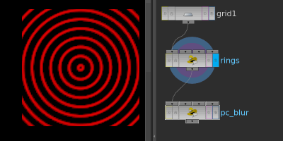
Download scene: Download file: pc_blur.hipnc
Another thing that I learned but didn't really understand, forgot, learned again, forgot, then feared for a while, and now finally have an understanding of (I think).
You have Cd on a grid, you want to blur it. One way is to iterate through each point, look at its neighbours, add up the result, and divide by the number of neighbours. Because it's a grid, and the point numbering is consistent, you could do something like
vex
int width = 50; // say the grid is 50 points wide
vector left = point(0,'Cd', @ptnum-1);
vector right = point(0,'Cd', @ptnum+1);
vector top = point(0,'Cd', @ptnum+50);
vector bottom = point(0,'Cd', @ptnum-50);
@Cd = left + right + top + bottom;
@Cd /= 4.0;
int width = 50; // say the grid is 50 points wide
vector left = point(0,'Cd', @ptnum-1);
vector right = point(0,'Cd', @ptnum+1);
vector top = point(0,'Cd', @ptnum+50);
vector bottom = point(0,'Cd', @ptnum-50);
@Cd = left + right + top + bottom;
@Cd /= 4.0;Works, but clunky, and it only works with a grid. Using the neighbour() and neighbourcount() functions is more generic (borrowed from odforce post):
vex
int neighbours = neighbourcount(0, @ptnum);
vector totalCd = 0;
for (int i = 0; i < neighbours; i++)
{
    int neighPtnum = neighbour(0, @ptnum, i);
    totalCd += point(0, "Cd", neighPtnum);
}
@Cd = totalCd/neighbours;
int neighbours = neighbourcount(0, @ptnum);
vector totalCd = 0;
for (int i = 0; i < neighbours; i++)
{
int neighPtnum = neighbour(0, @ptnum, i);
totalCd += point(0, "Cd", neighPtnum);
}
@Cd = totalCd/neighbours;Groovy, nice and generic now.
However, there's an even shorter cleaner way, using point clouds:
vex
int mypc = pcopen(0, 'P', @P, 1, 8);
@Cd = pcfilter(mypc, 'Cd');
int mypc = pcopen(0, 'P', @P, 1, 8);
@Cd = pcfilter(mypc, 'Cd');pcopen() is designed to open point cloud (.pc) files on disk, but by using the 0 reference, the wrangle will treat the incoming geo as a point cloud. You need to tell it how it will find values in the cloud, 99.999% of the time you'll look up positions in the cloud ('P') using the location of the current point (@P). It searches to a maximum distance (1), and returns a maximum number of points (8). Pcopen() returns a handle so you can refer to the point cloud later, here I store that in variable 'mypc'.
pcfilter() purpose is to look at the results from a point cloud, and return the filtered (blurred, averaged, call it what you want) result of the attribute you specify. Here, we tell it to use the cloud we just opened, and look up the Cd attribute. Because pcopen returned the closest 8 Cd results near the current point, pcfilter will return the average of those 8 points. In other words, we've just blurred Cd by its surrounding 8 points, essentially a 1 pixel blur.
Adding some channels, we can control the blur with a slider:
vex
float maxdist = ch('maxdist');
int blur = chi('blur');
int pc = pcopen(0, 'P', @P, maxdist, blur);
@Cd = pcfilter(pc, 'Cd');
float maxdist = ch('maxdist');
int blur = chi('blur');
int pc = pcopen(0, 'P', @P, maxdist, blur);
@Cd = pcfilter(pc, 'Cd');maxdist doesn't really affect the result, its more for speed; if you know the search never has to be greater than a certain distance, these point cloud functions can run a lot faster. Also note that pcfilter() does a more clever job than the neighbour based method earlier, it knows to give far away points less importance than closer points.
Another use for this is vex based smoothing function, try this on a box in polygon mesh mode with lots of axis divisions . The only difference here is rather than blurring Cd, we're blurring P:
vex
float maxdist = ch('maxdist');
int blur = chi('blur');
int pc = pcopen(0, 'P', @P, maxdist, blur);
@P = pcfilter(pc, 'P');
float maxdist = ch('maxdist');
int blur = chi('blur');
int pc = pcopen(0, 'P', @P, maxdist, blur);
@P = pcfilter(pc, 'P');There's a variety of functions to manipulate point clouds, most are prefixed with 'pc', so are handily grouped together in the vex docs: http://www.sidefx.com/docs/houdini15.0/vex/functions/ (skip down to the 'point clouds and 3d images' section)
Curious aside 1: The grid based way of doing this is basically what convolution filters do in image processing. A specific version of this that looks like an edge detect filter is called a laplacian filter, a word which I've seen come up now and then, but didn't really understand. Now I sorta do. More info: http://homepages.inf.ed.ac.uk/rbf/HIPR2/log.htm
Curious aside 2: If you've not used point clouds before, you might wonder why they exist, how are they better than doing point() or neighbour() lookups etc. They're just another way of storing 3d data, but by stripping out edges and polygons, some shortcuts can be taken to make certain operations be much faster. Getting the filtered results of sub-sections of geometry is one such operation, others are quickly iterating through near points, or approximating chunks of far away points with a simple average. The past 10 years of rendering has relied heavily on point clouds for effects like ambient occlusion and subsurface scattering, but have fallen out favour as brute force path tracing has become viable. Still, can be a handy trick for geometry processing in Houdini.
You want more? Better head to HoudiniVex2!