Appearance
Joy of Vex Day 17
copy sop, orient, quaternions
Orient
In the previous lesson we went learned how you can use @N and @up to define a stable rotation. There's another way to do this, which involves jumping to scary quaternion land, 4 dimensional values, unintuitive concepts.
Or is it? When I first heard about quaternions many years before getting into Houdini, I tried to understand the maths and got myself hopelessly confused, gave up. When I came back to it via Houdini and instance attributes, I took some advice from Matt Ebb; don't try and understand whats happening under the hood, just care about the end result, and what it can do for you. So some of this intro stuff you'll have to take on faith, I'll explain details later...
This is probably gonna be way over 30 mins today, but I think it's useful to have all the orient related stuff on a single page. Maybe break it over 2 days....
Orient basics
On the instance attributes page you'll see that orient is at the top of the list. That means it takes priority over everything else. The reason is that its the most unambiguous way to define rotation.
Orient is a 4 value vector, so it's nice and compact to store. The numbers themselves are gobbledygook for the most part, the only time I recognise what an orient is doing is when its at no rotation; the local x/y/z of each copy matches to the world xyz:
vex
@orient = {0,0,0,1}; @orient = {0,0,0,1};Try this on the usual grid, but put a transform sop before the wrangle. You can now rotate the grid however you want, and the boxes will always maintain their rotation.
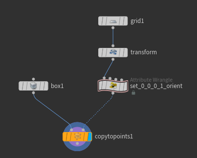
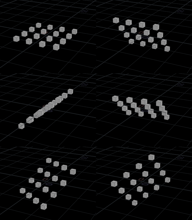
Defining orients from other things
That 'no rotation' orient is pretty much the only time you set an orient vector manually. Most of the time you construct an orient through vex functions. Vex offers several ways, each can be handy depending on the problem you're trying to solve. Most of these are done via the quaternion function.
To start with, lets go with angle and axis:
vex
 float angle = ch('angle');
 vector axis = chv('axis');

 @orient = quaternion(angle, axis);
float angle = ch('angle');
vector axis = chv('axis');
@orient = quaternion(angle, axis);Set the axis channel to (0,1,0), and slide the angle slider around, all the boxes will rotate around their y-axis. This is a much easier way to have smooth animated rotation compared to the @N and @up method from yesterday. Angle can now just be @Time:
vex
 float angle = @Time;
 vector axis = chv('axis');

 @orient = quaternion(angle, axis);
float angle = @Time;
vector axis = chv('axis');
@orient = quaternion(angle, axis);or just collapse it all down to one line::
vex
@orient = quaternion(@Time, chv('axis')); @orient = quaternion(@Time, chv('axis'));I still think that's pretty readable, you may think otherwise.
This also makes it easy to get per-copy offsets; take @ptnum, and multiply it by a offset channel, and add that to angle. If the offset slider is at 0 all the copied shapes will spin in unison, as you increase offset they'll be delayed relative to each other. (Back to multi lines because I've changed my mind, its easier to see this way):
vex
 float angle;
 vector axis;

 angle = ch('angle');
 angle += @ptnum*ch('offset');
 angle += @Time*ch('speed');

 axis = chv('axis');

 @orient = quaternion(angle, axis);
float angle;
vector axis;
angle = ch('angle');
angle += @ptnum*ch('offset');
angle += @Time*ch('speed');
axis = chv('axis');
@orient = quaternion(angle, axis);If I set the axis to 1 0 0, and play with the speed and offset sliders, I get this:
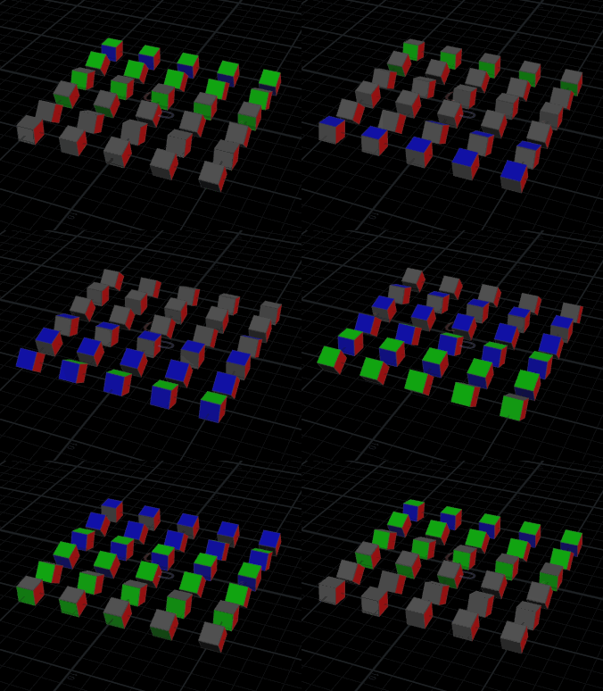
At this point I thought it'd be cool to make the axis be off at 45 degrees, so I set the axis to be 1 1 0:

That's cool but... wait, there's something not right; the rotation doesn't look even, it looks like its galloping, speeding up and slowing down. If you make the axis numbers even bigger, the effect becomes more pronounced, even on a single axis (this is 0 0 2):
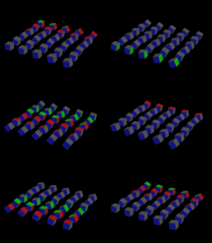
Remember way back when, I mentioned a lot of functions expect vectors to be normalized? This is one of those times. Throw in a normalize, things behave again:
vex
 float angle;
 vector axis;

 angle = ch('angle');
 angle += @ptnum*ch('offset');
 angle += @Time*ch('speed');

 axis = chv('axis');
 axis = normalize(axis);

 @orient = quaternion(angle, axis);
float angle;
vector axis;
angle = ch('angle');
angle += @ptnum*ch('offset');
angle += @Time*ch('speed');
axis = chv('axis');
axis = normalize(axis);
@orient = quaternion(angle, axis);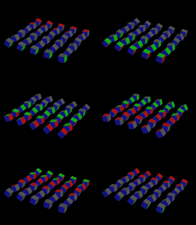
Orient via vector length
That gallop misfeature segues to another way to define a quaternion, with just an axis vector, no angle required. In this case, the vector length determines the rotation amount. Eg, take the axis, and multiply it by 0, you get no rotation (see how here we're only giving the axis vector to the quaternion function):
vex
 vector axis;
 axis = chv('axis');
 axis = normalize(axis);
 axis *= 0;

 @orient = quaternion(axis);
vector axis;
axis = chv('axis');
axis = normalize(axis);
axis *= 0;
@orient = quaternion(axis);Or if you multiply it by @Time, you get constant rotation:
vex
 vector axis;
 axis = chv('axis');
 axis = normalize(axis);
 axis *= @Time;

 @orient = quaternion(axis);
vector axis;
axis = chv('axis');
axis = normalize(axis);
axis *= @Time;
@orient = quaternion(axis);Seems odd, but if you think about it, its a very compact elegant way to define rotation. {1,0,0} and {5,0,0} both define the same axis along x, the only difference is the scale. Normally that scale (or length) of the vector would be discarded, but why not put it to use and make it mean something? That's what is going on with this quaternion format.
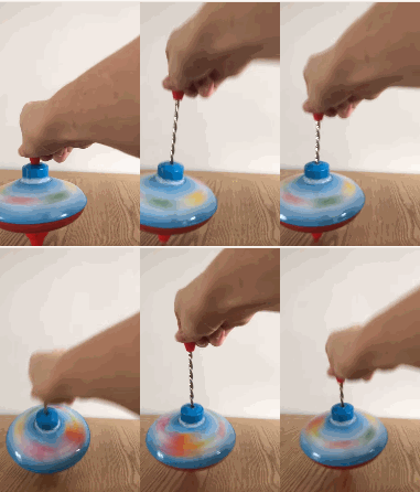
My mental picture of this is the old metal spinning tops; the handle is the axis, the length of the handle determines the spin. Well not exactly, but I loved those tops as a kid, so here, have a gif:
Something I've not explained yet is, what are the units of rotation we're using here? What if we want an exact 90 degree or 45 degree rotation?
You might've guessed by now that it uses radians, because all the big kids use radians. So to rotate 90 degrees, you naturally know that its 1.570795 radians:
vex
 vector axis;
 axis = chv('axis');
 axis = normalize(axis);
 axis *= 1.570795;

 @orient = quaternion(axis);
vector axis;
axis = chv('axis');
axis = normalize(axis);
axis *= 1.570795;
@orient = quaternion(axis);Oh? You didn't know it was 1.570795 radians? Nah, me neither. You can use the radians function to convert from degrees:
vex
 vector axis;
 axis = chv('axis');
 axis = normalize(axis);
 axis *= radians(90);

 @orient = quaternion(axis);
vector axis;
axis = chv('axis');
axis = normalize(axis);
axis *= radians(90);
@orient = quaternion(axis);Or you can meet in the middle, and remember that pi radians is 180 degrees, so pi/2 would be 90. A handy misfeature of the vex/hscript hodgepodge is that the vex wrangle text editor is treated similar to file path text fields and whatnot; if you were to put in things like $OS and $HIP they'd get replaced with the node name and the hip path before getting processed by vex. $PI is also recognised and replaced with Pi to about 10 decimal places, so we can do this:
vex
 vector axis;
 axis = chv('axis');
 axis = normalize(axis);
 axis *= $PI/2;

 @orient = quaternion(axis);
vector axis;
axis = chv('axis');
axis = normalize(axis);
axis *= $PI/2;
@orient = quaternion(axis);Update Jan 2023: Hello, Matt from the future again! At some point Sidefx added a few constants to wrangles, so just PI (all in capitals) works, no dollar sign required.
'What possible use is all this?' You may ask? Well, now we have a way to randomly rotate things at 90 degree values. We can do rand(@ptnum), which gives a random value between 0 and 1. Multiply that by 4, its random value between 0 and 4 (but remember it never gets to 4, at most it'll be 3.9999...). Truncate that, so its now exactly 0, 1, 2 or 3. Multiply that by $PI/2, you have everything rotated at exactly 0, 90, 180 or 270:
vex
 vector axis;
 axis = chv('axis');
 axis = normalize(axis);
 axis *= trunc(rand(@ptnum)*4)*$PI/2;

 @orient = quaternion(axis);
vector axis;
axis = chv('axis');
axis = normalize(axis);
axis *= trunc(rand(@ptnum)*4)*$PI/2;
@orient = quaternion(axis);Or use noise(@P) instead of rand(@ptnum), and animate it, you get patterns of 90 degree rotations that flow through the grid:
vex
 vector axis;
 axis = chv('axis');
 axis = normalize(axis);
 axis *= trunc(noise(@P+@Time)*4)*$PI/2;

 @orient = quaternion(axis);
vector axis;
axis = chv('axis');
axis = normalize(axis);
axis *= trunc(noise(@P+@Time)*4)*$PI/2;
@orient = quaternion(axis);Hmm, sort of works, but not as random as the rand one. This is a good chance to go through how to debug a problem like this...
Joy of Vex Day 17B
Make this rotation thing do what we want
So clearly its not broken, but its not quite behaving as it should. In cases like this, I'll move the most important part of the wrangle into an attribute, so I can see it in the geometry spreadsheet. Here, I'll take the noise(@P) bit and move it to an attribute '@a'. I think that I should see @a before it gets trunc'd, so I have a better idea of the range of values:
vex
 vector axis;
 axis = chv('axis');
 axis = normalize(axis);
 @a = noise(@P+@Time);
 axis *= trunc(@a*4)*$PI/2;

 @orient = quaternion(axis);
vector axis;
axis = chv('axis');
axis = normalize(axis);
@a = noise(@P+@Time);
axis *= trunc(@a*4)*$PI/2;
@orient = quaternion(axis);If I look in the geo spreadsheet and click the 'a' column to sort by that attribute, and tap it a few times to see the min and max, it becomes more obvious whats going on; while rand() is stochastic, meaning its evenly random for all values, noise tends to mostly sit around 0.5. Therefore it doesn't often get down as low as 0.1 or as high as 0.9, meaning once its multiplied by 4 and trunc'd, we mainly get the middle values (1 and 2), and rarely get the extreme values (0 and 3).
How to fix this? Well, one way would be to fit it, so we take the 0.4 to 0.6 range where most of the action is, and expand that out to 0 to 1:
vex
 vector axis;
 axis = chv('axis');
 axis = normalize(axis);
 @a = noise(@P+@Time);
 @a = fit(@a, 0.4, 0.6, 0, 1);
 axis *= trunc(@a*4)*$PI/2;

 @orient = quaternion(axis);
vector axis;
axis = chv('axis');
axis = normalize(axis);
@a = noise(@P+@Time);
@a = fit(@a, 0.4, 0.6, 0, 1);
axis *= trunc(@a*4)*$PI/2;
@orient = quaternion(axis);But personally I love a chramp, so that way I can interactively tweak the range to where I want:
vex
 vector axis;
 axis = chv('axis');
 axis = normalize(axis);
 @a = noise(@P+@Time);
 @a = chramp('noise_rerange',@a);
 axis *= trunc(@a*4)*$PI/2;

 @orient = quaternion(axis);
vector axis;
axis = chv('axis');
axis = normalize(axis);
@a = noise(@P+@Time);
@a = chramp('noise_rerange',@a);
axis *= trunc(@a*4)*$PI/2;
@orient = quaternion(axis);
You can think of moving the points of the ramp around like adjusting the brightness and contrast of an image; put the start and end points close together, you're increasing contrast. Move the range overall towards the left, you're effectively making most of the image dark, move it all to the right, you're making most of the image light. In this case by doing so you're biasing the likelihood of which values will get passed onto the rotation; an even spread of 0 1 2 3 , or mainly 0 and 1, or exclusively 3, or you could put more points in the ramp to make it skip the values 2 altogether. Very powerful.
So while here I was able to sort the data in the spreadsheet, other times its easier to see the attributes moving things around, or setting colours, or whatever is relevant to your case. Here, I might also make @a directly affect @P.y, to see how far they bob up and down, thus giving me an idea of how the rotation is being affected:
vex
 vector axis;
 axis = chv('axis');
 axis = normalize(axis);
 @a = noise(@P+@Time);
 @a = chramp('noise_rerange',@a);
 axis *= trunc(@a*4)*$PI/2;
 @P.y = @a;

 @orient = quaternion(axis);
vector axis;
axis = chv('axis');
axis = normalize(axis);
@a = noise(@P+@Time);
@a = chramp('noise_rerange',@a);
axis *= trunc(@a*4)*$PI/2;
@P.y = @a;
@orient = quaternion(axis);That's one of the key strengths of Houdini, you can very quickly visualise your data in a variety of ways.
Orient via N and up
So we've defined @orient via angle and axis, and axis+length of axis, what else? Well, we used @N and @up previously to define a stable rotation, surely there's a way to port that to a quaternion. And yes, there is:
vex
 @N = {0,1,0};
 float s = sin(@Time);
 float c = cos(@Time);
 @up = set(s,0,c);

@orient = quaternion(maketransform(@N, @up)); @N = {0,1,0};
float s = sin(@Time);
float c = cos(@Time);
@up = set(s,0,c);
@orient = quaternion(maketransform(@N, @up));So (as far as I know anyway) there's no way to go direct from N and up to a quaternion, but there is a way to go from N and up, to a matrix, and then to a quaternion. Maketransform will create a matrix, which we immediately pass to the quaternion function.
Orient via matrix
So obviously that means if we're ever in the unlikely scenario of having a matrix lying around that we've defined ourselves, that's yet another format we can directly pass to the quaternion function. We'll get to the finer points of matricies later, but for now, take this as a given:
vex
 matrix3 m = ident();
 @orient = quaternion(m);
matrix3 m = ident();
@orient = quaternion(m);Matricies come in 2 flavours, an all singing all dancing rotate/scale/transform/skew/perspective-adjust matrix, which is a 4x4 array of numbers, which vex calls a matrix. Then there's a smaller one that handles just rotation and scale, which is a 3x3 set of numbers, called a matrix3.
That little snippet creates a new matrix3 variable called m, and uses the ident() function, which means 'a matrix that does nothing'. That is, it has no rotation, and sets scale to 1,1,1.
We then pass that to the quaternion function, which will then pull out the rotation information, and construct our orient. In this case, that's the same as just going
vex
@orient = {0,0,0,1}; @orient = {0,0,0,1};Orient via euler values
You might want to define orient in terms of '30 degrees, around x, 10 around y, -23 around z', as if you were rotating things using a transform sop or the high level transform controls on objects. Vex has you covered with the eulertoquaternion function:
vex
 vector rot = radians(chv('euler'));
 @orient = eulertoquaternion( rot, 0);
vector rot = radians(chv('euler'));
@orient = eulertoquaternion( rot, 0);Euler rotations can be described in radians too, and thats what this function expects (which caught me out the first time I used it). So we have a chv to give an interface to the user, convert from degrees to radians with the radians function, then pass that vector to eulertoquaternion. The second variable (the 0) is to tell it what order to apply the rotations in, XYZ, YZX, ZXY etc... 0 tells it to work in XYZ order, which normally works as you expect.
Blending orients
So now we've covered hopefully every way you might have stored rotation and how to convert it to a quaternion. You might have a voice at the back of your head whispering 'Yeah but... so what? What does this gain me?'. One reason is that we now have a standard rotation format, so there's less chance that you'll be stuck when you have a part of your setup using @N, and others using euler rotations. A better reason is that there's several helper functions quaternions have that aren't easily matched by other rotation methods.
Say you had 2 quaternions, and you want to blend from one to the other. You can do this with slerp.
vex
 vector4 a = {0,0,0,1};
 vector4 b = quaternion({0,1,0}*$PI/2);
 @orient = slerp(a, b, ch('blend') );
vector4 a = {0,0,0,1};
vector4 b = quaternion({0,1,0}*$PI/2);
@orient = slerp(a, b, ch('blend') );Slide the blend channel slider, orient will smoothly interpolate.
Rather than use a slider, we could use @Time%1, so it'll smoothly animate from a to b, pop back to a, smoothly animate to b, pop back to a etc:
vex
 vector4 a = {0,0,0,1};
 vector4 b = quaternion({0,1,0}*$PI/2);
 float blend = @Time%1;
 @orient = slerp(a, b, blend );
vector4 a = {0,0,0,1};
vector4 b = quaternion({0,1,0}*$PI/2);
float blend = @Time%1;
@orient = slerp(a, b, blend );Or run @Time through a chramp, and draw in a triangle shape so it bounces between the a and b rotations:
vex
 vector4 a = {0,0,0,1};
 vector4 b = quaternion({0,1,0}*$PI/2);
 float blend = chramp('blendramp',@Time%1);
 @orient = slerp(a, b, blend );
vector4 a = {0,0,0,1};
vector4 b = quaternion({0,1,0}*$PI/2);
float blend = chramp('blendramp',@Time%1);
@orient = slerp(a, b, blend );The cool thing about slerp is that it always takes the shortest path between two orients, and does it in a very stable way. If you've ever suffered gimble lock, or euler flips, or weird rotation funk where you animate from 2 degrees to -358, and rather than taking the obvious short path, you'll find your animation takes the stupid long way round... all those problems don't affect slerp.
Here I've taken the random 90 degree example from earlier, and expanded it so that rather than popping between the values, it smoothly interpolates.
vex
 vector4 target, base;
 vector axis;
 float seed, blend;

 axis = chv('axis');
 axis = normalize(axis);
 seed = noise(@P+@Time);
 seed = chramp('noise_rerange',seed);
 axis *= trunc(seed*4)*$PI/2;

 target = quaternion(axis);
 base = {0,0,0,1};
 blend = chramp('anim',@Time%1);

 @orient = slerp(base, target, blend);
vector4 target, base;
vector axis;
float seed, blend;
axis = chv('axis');
axis = normalize(axis);
seed = noise(@P+@Time);
seed = chramp('noise_rerange',seed);
axis *= trunc(seed*4)*$PI/2;
target = quaternion(axis);
base = {0,0,0,1};
blend = chramp('anim',@Time%1);
@orient = slerp(base, target, blend);
Orient followed by transform sop
The first example here used a transform sop to rotate the grid, a wrangle to set orient, and you could see the boxes maintained their local rotation.
If you swap the order around, and put the transform after the orient wrangle, you'll see that they now inherit the rotation from the transform sop.
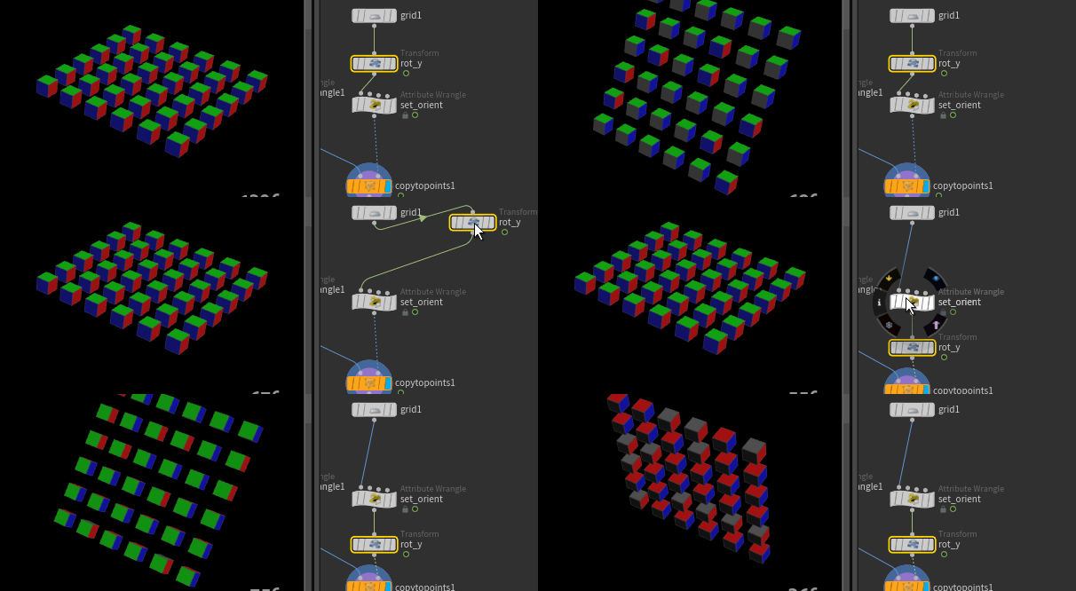
Why? Well, if you look at the transform sop, you've probably never noticed the 'Attributes' parameter beneath the 'Move centroid to origin' button.

It has a * in there, meaning the transform sop will affect all attributes it knows it can affect. You'd expect @P to be modifed by a transform sop of course, and if you think about it @N (otherwise if you rotated a box that had normals, the shading would go all screwy when the normals no longer match to the vertex positions).
@orient is also one of these attributes. If you don't want it, you can modify that attributes parameter to not include it with something like
* ^orient
For the most part though, this is a very handy thing to have, and will do what you expect.
Transform operations and attribute types
As an aside, why doesn't a transform sop affect @Cd? Well, houdini knows that certain attributes are linked to transforms, so P, N, orient, a few others. Clearly Cd shoudn't be affected, so its not on the list.
But really, its not the attribute names that it's watching for, its the attribute type. If you middle mouse click and hold on a node, you'll see a list of the attributes on the geometry, and their type (float, vector, vector4, int etc). When you create or modify the common attributes, Houdini will usually set them to the right type automatically. But its possible to override this manually (or as we found once, accidentally), and get odd behavior.
A co-worker was storing colours on geometry, but finding they were coming out with strange values in his render. On going through the setup, we found that he'd accidentally pushed his colours to @N, had a few transform sops, then back to @Cd, which meant the colours were being 'rotated' in nonsensical ways. He had made a particularly complicated setup, so its not an easy mistake to make!
There's extra related info here you might want to know (but can ignore if you don't), I'll put it at the bottom of this chapter.
Combine orients with qmultiply
Another handy trick for quaternions that is tricky to do via other means.
Here's a polygon sphere, uniform scale 5, frequency 2, with some pigs copy sop'd onto it, where @N is normalize(@P), and @up is {0,1,0};
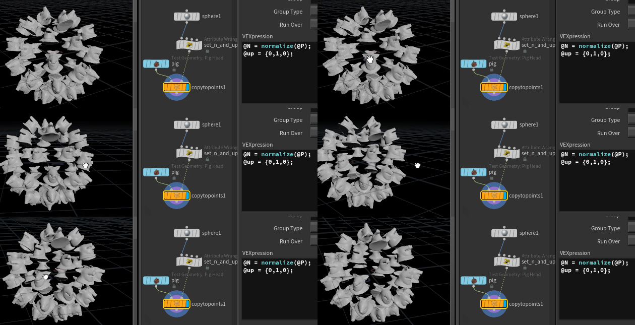
As per usual, its taken the local z-axis of the pig (which is along the snout of the pig), and aligned it with @N from the points (which is outwards from the sphere), so all the pigs are lying on their backs relative to the sphere.
Assume I don't want this though, and I want the pigs to be sitting with the top of their heads pointing away from the sphere. I could pre-rotate the pig with a transform sop and rotate it so the top of its head is pointing down the z-axis, its nose pointing along -Y, but what if you also want to then rotate each pig to turn left or right to talk to its neighbour? Or locally rotate an extra 20 degrees on Z? Or do a head bob?
You could start getting into multiple transform sops between the pig and the copy sop, and get into ugly stamp equations and all that, but there's a much neater way.
If you have 2 quaternions, qmultiply will give you the combined result of applying both. That's a bit vague when stated like that, here's a more practical and interesting way to explain it:
Take our sphere example, and construct an orient from @N and @up as we learned earlier:
vex
 @N = normalize(@P);
 @up = {0,1,0};
@orient = quaternion(maketransform(@N,@up)); @N = normalize(@P);
@up = {0,1,0};
@orient = quaternion(maketransform(@N,@up));Now construct another quaternion which is just the extra rotation we would have done with a transform sop after the pig; a rotation of 90 degrees around the x-axis. Lets use the angle and axis form of the quaternion function:
vex
vector4 extrarot = quaternion($PI/2, {1,0,0}); vector4 extrarot = quaternion($PI/2, {1,0,0});If we qmultiply the two quaternions together, this new rotation will be appended to the existing one, so each copy will be locally rotated 90 degrees around its local X-axis.
vex
@orient = qmultiply(@orient, extrarot); @orient = qmultiply(@orient, extrarot);This is more interesting to see if you map the angle onto a channel, and slide the extra rotation from 0 to 90. Here's the full wrangle, note that I'm now storing N and up as temp variables rather than attributes; once we create @orient they don't serve any purpose, no point keeping excess attributes around:
vex
 vector N, up;
 N = normalize(@P);
 up = {0,1,0};
 @orient = quaternion(maketransform(N,up));
 vector4 extrarot = quaternion(radians(ch('angle')),{1,0,0});

 @orient = qmultiply(@orient, extrarot);
vector N, up;
N = normalize(@P);
up = {0,1,0};
@orient = quaternion(maketransform(N,up));
vector4 extrarot = quaternion(radians(ch('angle')),{1,0,0});
@orient = qmultiply(@orient, extrarot);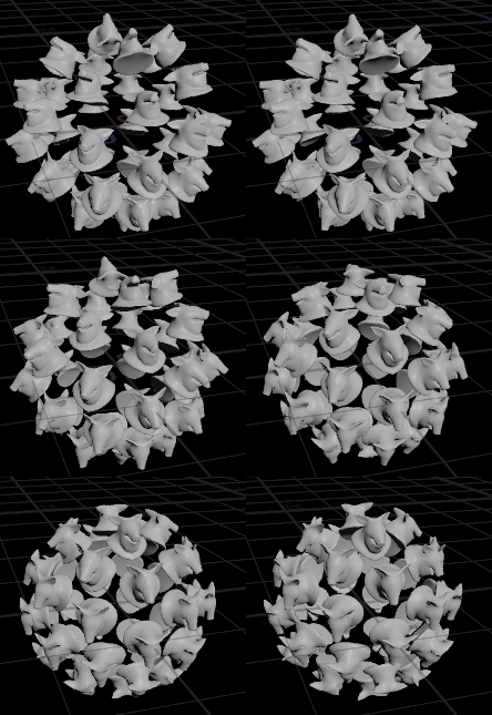
This is super powerful! We could now append a local rotation around each copy's Y-axis, so that the pigs looks like it disapproves of all this quaternion talk (some more code tidying too):
vex
 vector N, up;
 vector4 extrarot, headshake;

 N = normalize(@P);
 up = {0,1,0};
 @orient = quaternion(maketransform(N,up));
 extrarot = quaternion(radians(90),{1,0,0});
 headshake = quaternion(radians(20)*sin(@Time*3), {0,1,0});

 @orient = qmultiply(@orient, extrarot);
 @orient = qmultiply(@orient, headshake);
vector N, up;
vector4 extrarot, headshake;
N = normalize(@P);
up = {0,1,0};
@orient = quaternion(maketransform(N,up));
extrarot = quaternion(radians(90),{1,0,0});
headshake = quaternion(radians(20)*sin(@Time*3), {0,1,0});
@orient = qmultiply(@orient, extrarot);
@orient = qmultiply(@orient, headshake);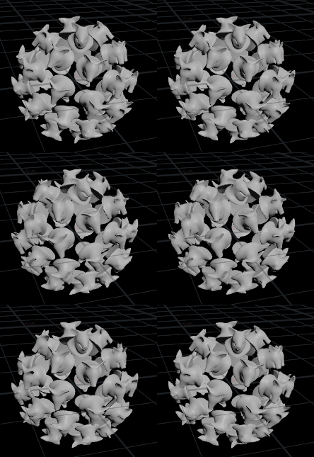
And some random z-axis rotation to show off:
vex
 vector N, up;
 vector4 extrarot, talktalk, wobble;

 N = normalize(@P);
 up = {0,1,0};
 @orient = quaternion(maketransform(N,up));
 extrarot = quaternion(radians(90),{1,0,0});
 talktalk = quaternion(radians(20)*sin(@Time*3), {0,1,0});
 wobble = quaternion({0,0,1}*curlnoise(@P+@Time*0.2));

 @orient = qmultiply(@orient, extrarot);
 @orient = qmultiply(@orient, talktalk);
 @orient = qmultiply(@orient, wobble);
vector N, up;
vector4 extrarot, talktalk, wobble;
N = normalize(@P);
up = {0,1,0};
@orient = quaternion(maketransform(N,up));
extrarot = quaternion(radians(90),{1,0,0});
talktalk = quaternion(radians(20)*sin(@Time*3), {0,1,0});
wobble = quaternion({0,0,1}*curlnoise(@P+@Time*0.2));
@orient = qmultiply(@orient, extrarot);
@orient = qmultiply(@orient, talktalk);
@orient = qmultiply(@orient, wobble);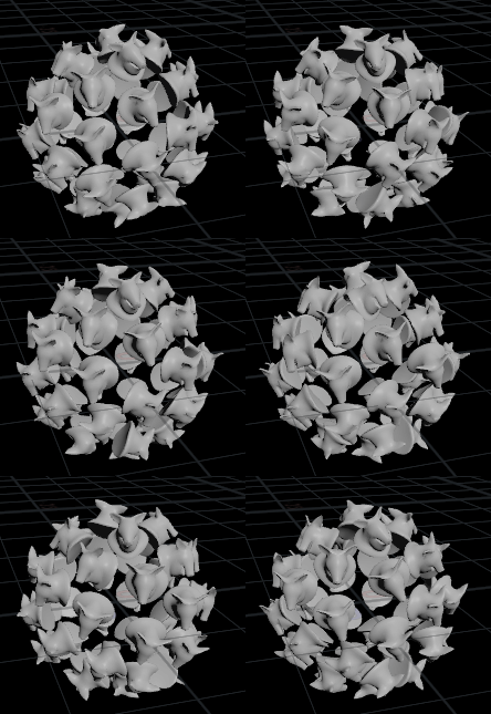
And so on. The ability to compose complex rotation out of small knowable components of rotation is a really powerful concept.
Convert back to matrix
Hopefully by now you're getting the concept that quaternions are a handy black box of rotation. That is, don't try and understand the numbers inside, just look at the end result. If the process to get you to the end result is simple, and the end result is what you're after, then there's no need to melt your brain trying to understand 4-dimensional rotations.
Which is fine, until the day that you have to debug your orients, and you really do need to understand what rotation values are being used.
In that case, you can still delay that Kahn Academy course, because the better way is to let vex convert quaternions into something human readable, with qconvert.
vex
matrix m = qconvert(@orient); matrix m = qconvert(@orient);Convert to N and up vectors
Well, human readable if you can read matricies, which I can't. In fact you probably want something a little more visual, like to generate @N and @up vectors. This is getting off into the weeds of vector maths which isn't my strong suit, but the idea is that now we have a matrix that represents our rotation, we can multiply a z-axis vector ( 0,0,1) against this matrix to generate @N, and a y-axis vector (0,1,0) to generate @up:
vex
 matrix3 m = qconvert(@orient);
 @N = {0,0,1}*m;
 @up = {0,1,0}*m;
matrix3 m = qconvert(@orient);
@N = {0,0,1}*m;
@up = {0,1,0}*m;Another way pointed out by Henry Foster is to just extract the components of the matrix directly:
vex
 matrix3 m = qconvert(p@orient);
 vector axes[] = set(m);
 @N = normalize(axes[2]); // z axis
 @up = normalize(axes[1]); // y axis
matrix3 m = qconvert(p@orient);
vector axes[] = set(m);
@N = normalize(axes[2]); // z axis
@up = normalize(axes[1]); // y axisWill you need this? Hopefully not, but nice to know that quaternions aren't a one way street.
Exercises
- Copy a bunch of eyeballs to a grid, make they them all look at a single point
- Extend the above one to give the eyballs 'saccades'; little random rotations to make them more lifelike
- Extend again so that you have a slider so that they can all look in random directions when the ch slider is at 0, but focus on a point when the slider is at 1
Bonus: transforms and attribute types
I mentioned before that applying a transform will modify @N, but won't modify @Cd. The reason isn't the attribute names, but the attribute type. While for the most part when using vex you just think of vectors as vectors, actually vex has several vector types. Some will be transformed, others won't. It's possible to change vector types with the setattribtypeinfo command. The help page also lists all the specific vector types vex has, and how they behave when transformed:
http://www.sidefx.com/docs/houdini/vex/functions/setattribtypeinfo.html
So if you get colours going weird when you rotate shapes, or normals refusing to update when you do the same, now you know to use setattribtypeinfo. 😃
---
prev: JoyOfVex16 this: JoyOfVex17 next: JoyOfVex18
main menu: JoyOfVex